Wednesday, November 30, 2011
1975 Fiat Wheel Alignment Guide
FIAT SPECIFICATIONS AND ADJUSTMENT
Before attempting to check or adjust wheel alignment, make sure tires are properly inflated. Refer to manufacturers specifications given in owner's manual.
CASTER
Model 131 and 128 (Except. Sport L) - If caster is not to specifications, raise front of vehicle. Remove stabilizer bar-to-control arm nut and disconnect control arm from body. Remove end of stabilizer bar from control arm. To adjust caster, addition of shims between end of stabilizer bar and rubber pad of control arm will decrease caster angle and removal of shims will increase caster angle. Reverse removal procedure and recheck caster.
Model 128 Sport L - If caster is not to specifications, adjust by adding or removing shims located between stabilizer bar bushing and frame.
Model 124 - If caster is not within specifications, raise front of vehicle and remove wheel and shock absorber. Using suitable tool (A.74174), compress spring to relieve lower control arm and loosen nuts holding control arm pivot bar to crossmember. To adjust caster, remove shims from front stud and move to rear stud to increase caster. To decrease caster, remove shims from rear stud and move shims to front stud. Reverse removal procedure and check caster.
Model X1/9 - If caster is not to specifications, adjust by adding or removing shims located between stabilizer bar and stabilizer bar support.
CAMBER
Model 124 - If camber is not within specifications, adjust by changing shims. Raise front of vehicle, remove wheel and shock absorber. Using suitable tool (A.74174), compress spring to relieve lower control arm and loosen nuts holding control arm pivot bar to crossmember. To increase camber, remove equal amount of shims from both studs and add equal amount of shims to decrease camber. NOTE - Adding or removing equal amounts of shims will not affect caster. Reverse removal procedure and check camber.
Model 128 and 131 Front - Camber is nonadjustable. If not within specifications, inspect suspension for damage and repair or replace parts as necessary.
Model 128 Rear - If rear camber is not within specifications raise rear of vehicle and compress one end of leaf spring, shifting it from flexible guide anchoring spring to control arm. Remove guide and slowly release spring. Remove nuts attaching pivot to body and loosen screw to free adjustment shims. To increase camber, add an equal number of shims on both screws attaching control arm to body. To decrease, remove equal number of shims from both screws. Reverse removal procedure and check camber.
Model X1/9 Front and Rear - Camber is nonadjustable. If not within specifications, inspect suspension for damage and repair or replace parts as necessary.
TOE-IN
Model 128, 131 and X1/9 Front - Place front wheels in straight-ahead position. If toe-in is not within specifications, loosen sleeve locking nut on tie rods. To adjust, rotate hexagon on ball pin to set toe-in specifications. Hold hexagon in position and lock nut against tie rod sleeve.
Model 128 Rear - If rear toe-in is not within specifications raise rear of vehicle and compress one end of leaf spring, shifting it from flexible guide anchoring spring to control arm. Remove guide and slowly release spring. Remove nuts attaching pivot to body and loosen screws to free adjustment shims. To increase to-in, add shims to rear screw or remove shims front front screw. To decrease, add shims to front screw or re3move shims from rear screw.
Model 124 Front - Place front wheels in straight-ahead position. If toe-in is not within specifications, loosen four clamps securing sleeves on tie rods. Rotate tie rods in opposite direction (by equal amounts) to set toe-in to specifications. Tighten clamp nuts. NOTE - Expansion slot in sleeve must coincide with clamp joint when clamp is fully tightened.
Model X1/9 Rear - If rear toe-in is not within specifications, loosen clamps securing sleeves to reaction rods. Adjust toe-in by lengthening or shortening reaction rods. Tighten clamps and recheck toe-in.

1963-73 Fiat Models Wheel Alignment Guide
1963-73 FIAT SPECIFICATIONS AND ADJUSTMENTS
TIRE INFLATION (COLD)
Before attempting to check or adjust wheel alignment, ensure that tires are inflated according to specifications

CASTER
Model 128 - If caster is not within specifications, raise front of vehicle. Remove anti-roll bar to control arm nut and disconnect control arm from body. Remove end of anti-roll bar from control arm. To adjust caster, addition of shims between end of anti-roll bar and rubber pad of control arm will decrease caster and removal of shims will increase caster. Reverse removal procedure and check caster.
Model 124 - If caster is not within specifications, raise front of vehicle and remove wheel and shock absorber. Using suitable tool (A.741174), compress spring to relieve lower control arm and loosen nuts holding control arm pivot bar to crossmember. To adjust caster, remove shims from front stud and move to rear stud to increase caster. To decrease caster, remove shims from rear stud and move shims to front stud. Reverse removal procedure and check caster.
Models 600D, 850 and 1100R - If caster is not within specifications, loosen two nuts on control arm pivot bar to body. To adjust, remove shims from rear stud and place shims at front stud to increase caster. To decrease caster, move shims from front stud to rear stud. Tighten nuts and check caster.
Model 1500 - No adjustment procedure available.
CAMBER
Model 124 - If camber is not within specifications, adjust by changing shims. Riase front of vehicle, remove wheel and shock absorber. Using suitable tool (A.74174), compress spring to relieve lower control arm and loosen nuts holding control arm pivot bar to crossmember. To increase camber, remove equal amount of shims from both studs and add equal amount of shims to decrease camber. NOTE - Adding or removing equal amounts of shims will not affect caster. Reverse removal procedure and check camber.
Model 1500 - No adjustment procedure available at time of this publication. See Wheel Alignment specifications.

Model 128 - Front - Camber is nonadjustable. If not within specifications, inspect suspension for damage. Repair or replace parts as necessary.
Model 128 Rear - If rear camber is not within specifications raise rear of vehicle and compress one end of leaf spring, shifting it from flexible guide anchoring spring to control arm. Remove guide and slowly release spring. Remove nuts attaching pivot to body and loosen screw to free adjustment shims. To increase camber, add an equal number of shims on both screws attaching control arm to body. To decrease, remove equal number of shims from both screws. Reverse removal procedure and check camber.
Models 600D, 850 and 1100R Front - If camber is not within specifications, adjust by changing shims. Loosen two nuts on control arm pivot bar to body. To increase camber, add equal amounts of shims to both studs and to decrease, remove equal amounts of shims. Tighten nuts and check camber.
TOE-IN
Model 128 Front - Place front wheels in straight-ahead position. If toe-in is not within specifications, loosen sleeve locking nut on tie rods. To adjust, rotate hexagon on ball pin to set toe-in specifications. Hold hexagon in position and lock nuts against tie rod sleeve.
Model 128 Rear - If rear toe-in is not within specifications raise rear of vehicle and compress one end of leaf spring, shifting it from flexible guide anchoring spring to control arm. Remove guide and slowly release spring. Remove nuts attaching pivot to body and loosen screws to free adjustment shims. To increase toe-in, add shims to rear screw or remove shims from front screw. To decrease, add shims to front screw or remove shims from rear screw.
All Other Models Front - Place front wheels in straight ahead position. If toe-in is not within specifications, loosen four clamps securing sleeves on tie rods. Rotate tie rods in opposite direction (by equal amounts) to set toe-in to specifications. Tighten clamps. NOTE - Expansion slot in sleeve must coincide with clamp joint when clamp is fully tightened.
Model 600D and 850 Rear - If rear is not within specifications, loosen screws securing lower control arm support to body. Elongated holes on support allow movement to set toe-in to specifications. Tighten screws 29-36 ft lbs. and check toe-in.
Tuesday, November 29, 2011
1974-75 Nissan Datsun Wheel Alignment Guide
DATSUN SPECIFICATIONS AND ADJUSTMENTS
TIRE INFLATION (COLD)
Before attempting to check or adjust wheel alignment, make sure that tires are properly inflated. Refer to manufacturer's specifications given in owner's manual.
RIDING HEIGHT
Pickup Only - Measure distance from center of lower control arm bushing (where it connects to body) and lower steering knuckle bushing (see illustration). To adjust, raise vehicle to release tension on anchor bolt adjusting nut and turn anchor bolt to adjust to specified height.
Riding Height Specifications
Application Inches (mm)
620 Pickup................................ 3.1-3.2 (72-82)
CASTER
All Models Exc. Pickup - Preset at factory and cannot be adjusted. If not to specifications, check suspension for wear or damage and repair or replace components as necessary.
Pickup - Caste is adjusted by increasing or decreasing thickness of shims inserted between upper link spindle and upper link mounting bracket. When front shim thickness increases, caster decreases. NOTE - Do not adjust caster with difference between front and rear shim thicknesses beyond .078" (2mm).
CAMBER
All Models (Exc. Pickup) - Preset at factory and cannot be adjusted. If not to specifications, check suspension for wear or damage and repair or replace components as necessary.
Pickup - Camber is adjusted bye increasing or decreasing the thickness of shims inserted between upper link spindle and upper link mounting bracket. When thickness of shims increase, camber decreases.
TOE-IN
All Models - Adjust by loosening each side steering link lock nut and adjusting steering link to change toe-in.
NOTE - Left and right side steering links should be adjusted equally. Tighten lock nuts.
1974 Datsun Models

1975 Nissan Datsun

1962-72 Nissan Datsun Wheel Alignment Guide
1962-72 DATSUN SPECIFICATIONS AND ADJUSTMENTS
TIRE INFLATION (COLD)Before attempting to check or adjust wheel alignment, ensure that tires are properly inflated.

RIDING HEIGHT
Pickups Only - Adjust to specificied distance by turning anchor bolt adjusting nut. Raise vehicle to release tension on adjusting nut.
 |
| Riding Height Measuring Point |
CASTER
All Models (Except 240Z, 510 and 1200) - Caster is adjusted by increasing or decreasing the thickness of shims inserted between upper link spindle and upper link mounting bracket. When front shim thickness increases, caster reduces. Set caster to specifications given in table. NOTE - Do not adjust caster with difference between front and rear shim thicknesses beyond .078".
240Z, 510 and 1200 - Caster is not adjustable. If alignment is not within specifications, check for damaged parts and replace as necessary
CAMBER
All Models (Except 240Z, 510 and 1200) - Camber is adjusted by increasing or decreasing the thickness of shim inserted between upper link spindle and upper link mounting bracket. When thickness of shims increases, camber reduces. Set camber to specifications given in table.
240Z, 510 and 1200 (Front) - Camber is not adjustable. If alignment is not within specifications, check for damaged parts and replace as necessary.
240Z and 510 (Rear) - Camber is not adjustable. If alignment is not within specifications, check for damaged parts and replace as necessary.
TOE-IN
All Models (Except Pickups) - Adjust by loosening side rod lock nuts and adjusting length of side rod to change toe-in to correct specifications. NOTE - Left and right side rods should be moved equally. Tighten lock nuts.
Pickups - Adjust by loosening cross rod lock nuts and turning cross rod to change its length which will increase or decrease the toe-in depending on the direction rod is turned. With toe-in to correct specifications, tighten lock nuts.

1971-72 Cricket Wheel Alignment Guide
1971-72 CRICKET SPECIFICATIONS AND ADJUSTMENTS
TIRE INFLATION
Before attempting to check or adjust front wheel alignments, ensure tires are properly inflated. Manfucturer recommended tire pressure is stenciled on inside of glove box door.
CASTER
Caster is not adjustable. If alignment is not within specification, inspect for damage parts and replace as necessary.
CAMBER
Camber is not adjustable. If alignment is not within specifications, inspect for damaged parts and replace as necessary.
TOE-IN
To adjust toe-in, loosen ball joint lock nuts on both tie rods. Loosen screws in rubber boot on inner ends of tie rod and ensure boots are free. Adjust tie rods to specifications (see chart). Tighten lock nut on tie rod end joints and center tie rods. Align boots and tighten clamps until boots are secure.

Monday, November 28, 2011
1972-76 Courier All Models Wheel Alignment Guide
1972-73 COURIER SPECIFICATIONS AND ADJUSTMENTS
TIRE INFLATION
Before attempting caster or camber adjustments, ensure tires are correctly inflated. Specifications are located on glove box door; especially consider radial tires, they require a different pressure than conventional tires.
NOTE - For reliable vehicle control, maintain specified difference between front and rear tire pressure.
NOTE - Vehicle must be unloaded, except fuel, water, and oil should be at their proper levels.
CASTER
To correct caster, adjust shims between upper control arm and frame or turn control arm shaft until correct angle is obtained (see specifications).
CAMBER
The camber is adjusted by adding or subtracting shims between the upper control arm and frame. Shims are available in the following sizes: .040", .064", .080", and .128". Set camber to specifications as shown in chart.
TOE-IN
The upward pointing of both front wheels which is necessary at offset the effects of camber. To adjust proceed as follows.
1) Raise vehicle until front wheels clear ground. Turn wheel by hand and scribe a line in cenber of each tire tred. Measure distance between marked lines. Both measurements must be taken at equal distances from ground.
2) If distance between wheels at rear is greater than that at front, but within specifications, adjustment is correct. If adjustment is wrong, loosen clamp bolts and adjust tie rod to specifications.
NOTE - Tighten clamping bolts with bolts horizontal and below steering link to prevent interference with center steering link.
FRONT WHEEL TURNING ANGLE
Front wheels should turn 37 degrees inward and 32 degrees outward. If necessary, adjust stop screws located at steering knuckle.
1972-73 Courier Models

1974-75 Courier Models

1971-75 Colt All Models Wheel Alignment
COLT SPECIFICATIONS AND ADJUSTMENTS
TIRE INFLATION (COLD)
Before attempting to check or adjust wheel alignment, ensure that tires are properly inflated. Refer to specifications in owners handbook.
CASTER
Caster is nonadjustable. If not within specifications, check front suspension for damage. Repair or replace parts as necessary.
CAMBER
Camber is nonadjustable. If not within specifications, check front suspension for damage. Repair or replace parts as necessary.
TOE-IN
Position wheels in straight-ahead position. If toe-in is not within specifications, loosen locking nuts on tie rod turn buckels. To adjust, rotate turn buckels until toe-in is within specifications. Tighten lock nuts. NOTE - Adjustment must be made equally to both sides of vehicle to maintain correct wheel lock angles; difference of tie rod length when adjusted should not exceed. 20".
1971-73 Colt Models

1974 Colt Models

1975 Colt All Models

1974 Capri Wheel Alignment
CAPRI SPECIFICATIONS AND ADJUSTMENT
TIRE INFLATION (COLD)
Before attempting to check or adjust wheel alignment, make sure that tires are properly inflated. Refer to manufacturers specifications, located inside glove box door.
CASTER
All Models - Caster is nonadjustable. If not within specifications, check front suspension for damage. Repair or replace parts as necessary.
CAMBER
All Models - Camber is non adjustable. If not within specification, check front suspension for damage. Repair or replace parts as necessary.
TOE-IN
All Models - Position wheels in straight-ahead position and loosen tie rod end lock nut and clips securing bellows. To adjust toe-in, rotate tie rods until specifications are within limits. Tighten lock nuts and secure clips. Tie rods lengths should be equal within 1/4".
1974 Capri Models

1975 Capri Models

1970-73 Capri All Models Wheel Alignment
1970-73 CAPRI SPECIFICATIONS AND ADJUSTMENTS
TIRE INFLATION (COLD)
Before attempting to check or adjust wheel alignment, ensure that tires are properly inflated. Refer to manufacturers specifications located on right hand sun visor.
CASTER
All Models - Caster is nonadjustable. If not within specifications, check front suspension for damage. Repair or replace parts as necessary.
CAMBER
All Models - Camber is non adjustable. If not within specifications, check front suspension for damage. Repair or replace parts as necessary
TOE-IN
All Models - Position wheels in straight ahead position and loosen tie rod end lock nut and clips securing bellows. To adjust toe-in, rotate tie rods until specifications are within limits. Tighten lock nuts and secure clips. Tie rods should be equal within 1/4".

1976 Import Models Wheel Bearing Adjustment Guide
ARROW AND COLT
All Models - Tighten adjusting nut to 14.5 ft. lbs. After seating bearing components, loosen nut to 0 ft. lbs. Now make final adjustment to 3.6 ft. lbs. After installing lock cap, insert cotter pin. NOTE - Do not loosen adjusting nut more than 15 degrees to align spindle holes.
AUDI
NOTE - The following procedure can only be performed using special tools indicated.
Model 100 (Front) - 1) Raise and support front of vehicle. Remove lower wheel bolt and replace with special wheel bolt adapter (V-104) and special dial indicator (G-43). By means of retaining screw on special tool (V-104), adjust dial indicator to pretensioned position of 1 millimeter.
2) Grasp wheel at front and rear. First push inward on front while pulling outward on rear, record dial indicator reading. Reverse this procedure and record dial indicator reading. Difference between these two reading is wheel bearing play. If play exceeds .04-.07 mm, adjustment will be necessary.
3) Remove cotter pin and castle nut. If there was too much play, tighten spindle nut until play is within specifications. If there was insufficient play, remove wheel, spindle nut and its shim. Replace and tighten spindle nut. Using 1 millimeter feeler gauge, loosen spindle nut until it is possible to insert feeler gauge between spindle nut and wheel hub. Attach special hub puller (V-26) and withdraw hub until it is firmly in contact with spindle nut. Remove puller and retighten spindle nut until it is within specifications
Model 100 (Rear) - Raise and support rear of vehicle. Remove grease cup and one wheel bolt. Attach special dial indicator (30-43), using wheel bolt adapter (40 - 104) and attachment (10-22). Dial indicator actuator foot should be pretensioned to 1 millimeter against the stub axle. Grasp wheel at front and rear. Move wheel on horizontal axis. If reading on dial indicator is not .02-.04 mm, adjustment will be necessary. Adjust by loosening or tightening spindle nut.
NOTE - Fox front wheel bearing is not adjustable. Torque stub axle nut to 13 ft. lbs.
Fox (Rear) - Remove grease cup, cotter pin and castle nut. Tighten spindle nut and loosen for adjustment. Adjust by lightly tightening spindle nut until plain washer (beneath spindle nut) can just be moved from side to side, using screwdriver. This adjustment will be correspond to .0012-.0027" (.03-.06 mm) wheel bearing play.
BMW
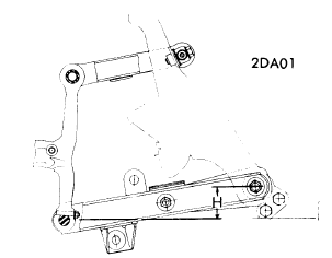
2002 Models - While rotating wheel hub, tighten castle nut to 22-24 ft. lbs., then rotate hub at least two more times. Loosen castle nut until bearing end play is noticed. Tighten castle nut to a maximum of 2.2 ft. lbs., then loosen nut to nearest hole and install cotter key. NOTE - After adjustment slotted washer should move easily, without noticeable resistance.3.0 Si and 530i Models - While rotating wheel hub, tighten castle nut to 7 ft. lbs. Loosen castle nut approximately 1/4 turn. Insert screwdriver in recess of bearing retainer washer and ensure washer can be rotated easily. Install suitable gauge holder (BMW 00 2 500) on wheel hub and install dial indicator with tip touching front axle stub. Move wheel hub back and forth several times and check bearing end play. Adjust castle nut until bearing end play is .0008-.0024". NOTE - Set bearing end play as close to lowest limit as possible. Install cotter key.
CAPRI
All Models - Rotate wheel, hub, and drum assembly while turning adjusting nut to 17-25 ft. lbs. Back off nut one-half turn. Retighten adjusting nut to 10-15 INCH lbs. Reinstall cotter pin and check front wheel rotations.
COURIER
All Models - While rotating wheel, hub and drum assembly, tighten adjusting nut to 17-25 ft. lbs. Back adjusting nut off 1/2 turn and retighten nut to 6-8 ft. lbs. Install new cotter key and check wheel rotation.DATSUN
All, Except F10 - Tighten spindle nut to torque specifications in table. Spin wheel and retorque spindle nut. Loosen nut according to specification in table and then tighten to align cotter key hole. Insert cotter key.F10 - Raise vehicle and place on safety stands. Remove tire and wheel. Make sure mounting nut is torqued to 87-145 ft. lbs. (12-20 mkg). Spin wheel hub several times in both directions to ensure free rotation. Measure bearing preload by attaching a spring pull scale to lug stud and turning hub. It should take about 3-11 lb. (1.4-4.9 kg) to turn hub.
FIAT
Model 124 and 131 - While rotating hub, torque spindle nut to 14.5 ft. lbs. Completely loosen nut and retighten to 5 ft. lbs. Loosen nut 30 degrees and stake collar of spindle nut into machined slot on spindle. Attach dial indicator with magnetic base on brake drum and actuating foot on spindle. Hub end play should not exceed .004" NOTE - When ever spindle nut has been removed it must be replaced with a new nut.Models 128 and X1/9 - Tighten front and rear spindle nuts to 112 ft. lbs. When spindle nuts are properly tightened, stake collar of spindle nut into machined slot on spindle.
1975 BMW Models Wheel Alignment Guide
BMW SPECIFICATIONS AND ADJUSTMENTS
TIRE INFLATION (COLD)
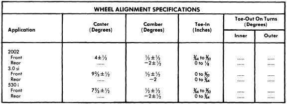
Before attempting to check or adjust wheel alignment, ensure tires are properly inflated. The 2002 series requires 26 psi front and rear. The 3.0 series require 30 psi front and rear. The 530i series requires 28 psi front and 26 psi rear.
CASTER AND CAMBER
All Models - Before checking caster and camber, vehicle must be in loaded condition. Loaded condition consists of two 143 lbs. weights on front seat, one 143 lbs. weight on rear seat, gas tank full and 66 lbs. on left side of luggage compartment. If caster and camber are not within specifications check suspension for damage. Repair or replace parts as necessary.
TOE-IN
All Models - Before checking toe-in, vehicle must be in loaded condition (see Caster and Camber). Check toe-in with front wheels in straight-ahead position. If not within specifications, loosen tie rod clamping bolts. Rotate both tie rod tubes until toe-in is within specifications. Tighten clamping bolts.
Sunday, November 27, 2011
1976 Import Models Wheel Alignment Guide
BMW
TIRE INFLATION (COLD)
Before attempting to check or adjust wheel alignment, ensure tires are properly inflated. The 2002 series requires 26 psi front and rear. The 3.0 series requires 30 psi front and rear. The 530i series requires 28 psi front and 26 psi rear.
CASTER AND CAMBER
All Models - Before checking caster and camber, vehicle must be in loaded condition. Loaded condition consists of two 143 lbs. weights on front seat, one 143 lbs. weight on rear seat, gas tank full and 66 lbs. on left side of luggage compartment. If caster and camber are not within specifications check suspension for damage. Repair or replace parts as necessary.
TOE-IN
All Models - Before checking toe-in, vehicle must be in loaded condition (see Caster and Camber). Check toe-in with front wheels in straight-ahead position. If not within specifications, loosen tie rod clamping bolts. Rotate both tie rod tubes until toe-in is within specifications. Tighten clamping bolts.
CAPRI
ADJUSTMENT
TIRE INFLATION (COLD)
Before attempting to check or adjust wheel alignment, make sure that tires are properly inflated. Refer to manufacturer's specifications, located inside glove box door.
CASTER
All Models - Caster is nonadjustable. If not within specifications, check front suspension for damage. Repair or replace parts as necessary
CAMBER
All Models - Camber is nonadjustable. If not within specifications, check front suspension for damage. Repair or replace parts as necessary.
TOE-IN
All Models - Position wheels in straight-ahead position and loosen tie rod end lock nut and clips securing bellows. To adjust toe-in, rotate tie rods until specifications are within limits. Tighten lock nuts and secure clips. Tie rods lengths should be equal within 1/4".
COURIER
TIRE INFLATION
Before attempting caster or camber adjustment, ensure tires are correctly inflated. Specifications are located on glove box door; especially consider radial tires, they require a different pressure than conventional tires.
NOTE - Vehicle must be unloaded, except fuel, water and oil should be at their proper levels.
CASTER
To correct caster, adjust shims between upper control arm and frame or turn control arm shaft until correct angle is obtained (see specifications).
CAMBER
The camber is adjusted by adding or subtracting shims between the upper control arm and frame. Shims are available in the following sizes: .040", .064", .080", and .128". Set camber to specifications as shown in chart.
TOE-IN
1) Raise vehicle until front wheels clear ground. Turn wheel by hand and scribe a line in center of each tire thread. Measure distance between marked lines in front of front wheel and at rear of front wheel. Both measurements must be taken at equal distances from the ground.
2) If distance between wheels at rear is greater than that at front, but within specifications, adjustment is correct. If adjustment is wrong, loosen clamp bolts and adjust tie rod to specifications.
NOTE - Tighten clamping bolts with bolts horizontal and below steering link to prevent interference with center steering link.
DATSUN
ADJUSTMENT
TIRE INFLATION (COLD)
 |
| Fig. 1 Pickup Front Suspension Riding Height Measurement Points. |
Pickup Only - Make measurement with vehicle empty: Fuel tank full, radiator filled, oil levels up to marks, spare tire and hardware in position. Measure distance from center of lower control arm bushing (where it contacts to body) and lower steering knuckle bushing (See "H" in Fig. 1). To adjust, raise vehicle to release tension on acnhor bolt ajdusting nut and turn anchor bolt to adjust to specified height.
CASTER
All Models Exc. Pickup - Preset at factory and cannot be adjusted. If not to specifications, check suspension for wear or damage and repair or replace components as necessary.
Pickup - Caster is adjusted by increasing or decreasing thickness of shims inserted between upper link spindle and upper link mounting bracket. When front shim thickness increases, caster decreases. NOTE - Do not adjust caster with difference between front and rear shim thickness beyond .079" (2 mm).
CAMBER
All Models (Exc. Pickup) - Preset at factory and cannot be adjusted. If not to specifications, check suspension for wear or damage and repair or replace components as necessary.

Pickup - Camber is adjusted by increasing or decreasing the thickness of shims inserted between upper link spindle and upper link mounting bracket. When thickness of shim increase, camber decreases.
TOE-IN
All Models Except Pickup - Adjust by loosening each side steering link lock nut and adjusting steering link to change toe-in. NOTE - Left and right side steering links should be adjusted equally. Tighten lock nuts.
Pickup - Adjust by loosening steering cross link lock nuts, and adjust steering cross link to to change toe-in. Tighten lock nuts.
FIAT
ADJUSTMENT
TIRE INFLATION (COLD)
Before attempting to check or adjust wheel alignment, make sure tires are properly inflated. Refer to manufacturers specification given in owner's manual.
CASTER
Model 131 and 128 (Except. Sport L) - If caster is not to specifications, raise front of vehicle. Remove stabilizer bar-to-control arm nut and disconnect control arm from body. Remove end of stabilizer bar from control arm. To adjust caster, addition of shims between end of stabilizer bar and rubber pod of control arm will decrease caster angle and removal of shims will increase caster angle. Reverse removal procedure and recheck caster.
Model 128 Sport L - If caster is not to specifications, adjust by adding or removing shims located between stabilizer bar bushing and frame.
Model 124 - If caster is not within specifications, raise front of vehicle and remove wheel and shock absorber. Using suitable tool (A.74174), compress spring to relieve lower control arm and loosen nuts holding control arm pivot bar to crossmember. To adjust caster, remove shims from front stud and move to rear stud to increase caster. To decrease caster, remove shims from rear stud an move shims to front stud. Reverse removal procedure and check caster.
Model X1/9 - If caster is not to specifications, adjust by adding or removing shims located between stabilizer bar and stabilizer bar support.
CAMBER
Model 124 - If camber is not within specifications, adjust by changing shims. Raise front of vehicle, remove wheel and shock absorber. Using suitable tool (A.74174), compress spring to relieve lower control arm and loosen nuts holding control arm pivot bar to crossmember. To increase camber, remove equal amount of shims form both studs and add equal amount of shims to decrease camber. NOTE - Adding or removing equal amount of shims will not affect caster. Reverse removal procedure and check camber.
Model 128 and 131 Front - Camber is nonadjustable. If not within specifications, inspect suspension for damage and repair or replace parts as necessary.
Model 128 Rear - If rear camber is not within specifications raise rear of vehicle and compress one end of leaf spring, shifting it from flexible guide anchoring spring to control arm. Remove guide and slowly release spring. Remove nuts attaching pivot to body and loosen screw to free adjustment shims. To increase camber, add on equal number of shim on both screws attaching control arm to body. To decrease remove equal number of shims from both screws. Reverse removal procedure and check camber.
BMW 1966-73 Models Wheel Alignment Guide
1966 TO 1973 BMW SPECIFICATIONS AND ADJUSTMENTS
TIRE INFLATION (COLD)
Before attempting to check or adjust wheel alignment, ensure that tires are properly inflated.

CASTER AND CAMBER
All Models - Before checking caster and camber, vehicle must be in loaded condition consists of two 143 lbs. weights on front seat, one 143 lbs. weight on rear seat, gas tank full and 66 lbs. on left side of luggage compartment. If caster and camber are not within specifications check suspension for damage. Repair or replace parts as necessary.
TOE-IN
All Models - Before checking toe-in, vehicle must be in loaded condition (see Caster and Camber). Check toe-in with front wheels in straight ahead position. If not within specifications, loosen tie rod clamping bolts. Rotate both tie rod tubes until loosen tie rod clamping bolts. Rotate both tie rod tubes until toe-in is within specifications. Tighten clamping bolts.

Austin Wheel Alignment Guide 1975
AUSTIN SPECIFICATIONS AND ADJUSTMENT
TIRE INFLATION (COLD)
Before attempting to check or adjust wheel alignment, make sure that tires are properly inflated. All models require 26 psi in front and 28 psi in rear.
RIDING HEIGHT
With vehicle on level surface, measure distance from center wheel bearing grease cap to bottom of fender well (in vertical line). If distance is not 15± ¼", adjustment must be made. Adjust bye removing lock bolt in torsion bar adjuster, loosen lock nut on adjuster screw and turn adjuster screw clockwise to increase height or counterclockwise to lower height. Replace lock bolt.
CASTER
Caster is nonadjustable.
CAMBER
Camber is nonadjustable.
TOE-IN
With vehicle unladen and tires properly inflated, set steering wheel in straight-ahead position. Measure difference between front of front wheel and rear of front wheels. If difference is not 1/14", adjust each steering link equally to obtain correct specifications.

Audi Wheel Alignment Guide 1975 Models
AUDI SPECIFICATIONS AND ADJUSTMENTS
TIRE INFLATION (COLD)
Before attempting to check and adjust wheel alignment, ensure tires are properly inflated. Model 100 requires 26 psi in front and 28 psi in rear. Fox requires 24 psi in front and 27 psi in rear.
CASTER
Fox - Caster angle is not adjustable. However, if not to specifications, check suspension for wear or damage and repair or replace necessary components
Model 100 - Caster and camber adjustment must be made at the same time. See Camber adjustment procedure.
CAMBER
Fox - With vehicle loaded down or placed on blocks, measure camber angle. If not to specifications, adjust by loosening ball joint mounting bolts and moving ball joint sideways on control arm until correct camber is obtained. Tighten ball joint mounting bolts and recheck camber angle.
Model 100 - 1) With vehicle equipped with spare tire and full fuel tank, measure caster and camber angle. If not to specifications, remove inner ball joint-to-lower control arm mounting bolt and install camber adjusting tool (US 9020) as shown in Fig. 1. Install slightly tighten on 8mm bolt and washer in threaded hole between inner and outer ball joint mounting bolts on lower control arm, then loosen outer mounting bolt. Tighten tensioner bolt on adjusting tool to break loose ball joint, then tighten or loosen tensioner bolt until camber angle is set to specifications.
2) To adjust caster angle, leave camber adjusting tool installed to maintain adjusted camber angle, then install caster adjusting tool as shown in Fig. 1. Adjust caster angle to specifications by moving ball joint forward or backward by means of adjusting tool. Hold tool stationary and tighten outer ball joint mounting bolt to 80 ft. lbs. (11 mkg). Remove caster and camber adjusting tools and tighten inner bolt to 47 ft. lbs. (6.5 mkg), then remove 8 mm bolt and washer.
 |
| Fig. 1 Adjusting Caster and Camber on Audi 100 |
TOE-IN
All Models - Before checking toe-in, check wheel rim run-out and replace rim if necessary. If toe-in is not to specifications, adjust by loosening tie rod outer locking nut and clamp and turning tie rods until correct toe-in is obtained. Tighten lock nut and clamp and recheck toe-in.

1974 Audi Wheel Alignment Guide
AUDI SPECIFICATIONS AND ADJUSTMENT
TIRE INFLATION (COLD)
Before attempting to check and adjust wheel alignment, make sure tires are properly inflated. Model 100 requires 28 psi in front and 26 psi in rear. Fox requires 28 psi in front and 24 in rear
CASTER
Fox - Caster angle is not adjustable. However, if not to specifications, check suspension for wear or damage and repair or replace necessary components.
Model 100 - Caster is determined from difference in camber at 20 degrees left and 20 degrees right wheel lock. Caster is negative if the left wheel at right lock shows larger camber than at left lock. Caster is considered positive if left wheel at left lock shows a larger camber than at right lock. Adjust by loosening lock nut "D" and turning eccentric bolt "E". Be sure to adjust equally on both sides and retighten lock nut (see illustration).
CAMBER
Fox - With vehicle loaded down or placed on blocks, measure camber angle. If not to specifications, adjust by loosening ball joint mounting bolts and moving ball joint sideways on control arm until correct camber is obtained. Tighten ball joint mounting bolts and recheck camber angle.
Model 100 - With wheel in straight-ahead position, measure camber angle. If not to specifications adjust by loosening lock nut "B", and bolt "C", and turning eccentric nut "A"
 |
| CASTER AND CAMBER ADJUSTING POINTS 100LS |
TOE-IN
All Models - Before checking toe-in, check wheel rim run-out and replace rim if necessary. If toe-in is not to specifications, adjust by loosening tie rod outer locking nut and clamp and turning tie rods until correct toe-in is obtained. Tighten lock nut and clamp and recheck toe-in.

Thursday, November 24, 2011
Audi Wheel Alignment Guide 1970-73
1970-73 AUDI SPECIFICATIONS AND ADJUSTMENTS
TIRE INFLATION (COLD)
Before attempting to check or adjust wheel alignment, ensure that tires are properly inflated. Model 100 and 100 LS require 26 psi (1.827 kg/cm2) in front and rear tires. Model S90 and Fox require 24 psi (1.687 kg/cm2) in front and rear tires.
RIDING HEIGHT
S90 (Front) - With vehicle unloaded and on level ground, check front ground clearance from floor to center of lower wishbone bearing support. If measurement is not within specifications, turn adjusting screw on crossmember to correct height. Both sides must be adjusted to specifications.
S90 (Rear) - Rear riding height is nonadjustable. Measure at lower edge of frame cross tube to floor. If measurement is not within specifications, check for damage to suspension components.
100 and 100LS - With wheel in straight ahead position, measure camber angle. If not to specifications, adjust by loosening lock nut "B", bolt "C" and turning eccentric nut "A".
Fox - With vehicle loaded down or placed on blocks, measure camber angle. If not to specifications, adjust by loosening both mounting bolts use suitable tool (Audi 40-200).
Fox - Check wheel rims for runout and replace as necessary. Measure distance between front edges of front rims and rear edges of front rims. Difference in these two measurements is toe-in. If not within specifications, adjust tie-rod (located just behind steering rack).
100LS (Front) - With vehicle unloaded and on level ground, check front ground clearance from floor to front bearing shell of lower wishbone. If distance is lower than specifications, correct riding height. Remove coil spring assembly from vehicle and shock absorber from coil spring assembly. For removal and installation procedures see Coil Spring/Shock Absorber Assembly in Suspension Section. Install spaces in position on shock absorber shaft to adjust ground clearance. Each spacer gives .393" (9.98 mm) increase in clearance. Assemble and install coil spring assembly and shock absorber into vehicle.
100LS (Rear) - With vehicle unloaded and on level ground , check rear ground clearance at lower edge of frame cross tube to floor. If not within specifications, adjust torsion bar.
100 (Front) - Measure clearance from ground to lower edge of front engine platform mounting bolt head. If height is not to specifications, adjust by adding spacers to coil spring
Fox (Rear) - Measure clearance form ground to lower domed surface of body next to control arm bushing. If clearance is less than specified, install heavier springs.


CASTER
NOTE - Before checking or adjusting wheel alignment, vehicle must be under specified loaded conditions (see Riding Height, All Models).
S90 - To adjust, loosen nut on upper wishbone to mounting bracket screw. Turn eccentric to change caster angle. Eccentric moving rear wishbone joint forward increases caster and reverse movement decreases caster. Torque lock nut to 542 ft. lbs. (7.49 mkg) when caster is within specifications.
100 and 100LS - Caster is determined from difference in camber at 20 degrees left and 20 degrees right wheel lock. Caster is negative if lewft wheel at right lock shows larger camber than at left lock. Caster is considered positive if left wheel at left shows a larger camber than at right lock. Adjust by loosening lock nut "D" and turning eccentric bolt "E". Be sure to adjust equally on both sides and retighten lock nut (see illustration).
Fox - Caster angle is not adjustable. However, if not to specifications, check suspension for wear or damage. Repair or replace necessary components.
CAMBER
NOTE - Before checking or adjusting wheel alignment, vehicle must be under specified loaded conditions (see Riding Height, All Models).
S90 - To adjust, loosen nut on upper wishbone to mounting bracket screw. Rotate adjusting tube to change camber angle. When wishbone joint moves away from center of vehicle, camber increases and reverse movement decreases camber. Torque lock nut to 54.2 ft. lbs. (7.49 mkg) when camber within specifications.
TOE-IN
 |
| Caster and Camber Adjusting Points 100LS |

Wednesday, November 23, 2011
1965 Import Vehicles Jacking and Hoisting Guide
ALL MANUFACTURERS
NOTE - These illustrations are not intended to represent exact structure of the manufacturer's frame, underbody, or body outline. These are presented only to give the mechanic some point of reference
FRAME AND UNDERBODY
The following illustrations indicate areas (parts) of the underbody and frame which may be used to raise and support the vehicle, using either floor jack or hoist. These points are indicated by shaded areas on the frame (see sample illustration).
OUTERBODY
Those points designated on the outline of the body were specifically designed to facilitate the use of the vehicle's own jack, but may also be used to raise and support the vehicle by means of floor jack or hoist. These jacking points are indicated by circular dots on the outline of the body (see sample illustration). If floor jack or hoist is employed, extreme care should be exercised to prevent damaging the outer body shell.


1965 Import Vehicles Ball Joint Checking Guide
ARROW / COLT
All Models - With components removed from control arm and ball joint still installed, check following: Horizontal and vertical free play (0"), and ball joint rotation starting torque 4-6 ft. lbs. (6-8Nm). Replace ball joints if correct specifications are not obtained
AUDI
Fox - Clearance of ball joint with pressure applied by leverage should be .04-.10" (1.0-2.5 mm). if not replace ball joints
BMW
All Models - With lower control arm removed, measure axial (up and down) movement of ball joint stud. If movement exceeds .0945", replace ball joint.
COURIER
All Models - Check working surfaces of ball joints and studs for wear or damage. End play should not exceed .031" (.8 mm), if end play is excessive, replace ball joint.
DATSUN
All Models (Exc. 620 Pickup) - Remove lower control arm. Use appropriate spring tension gauge and and attach it to top of ball joint stud nut. Measure force (INCH Lbs.) required to move ball joint stud laterally. If measurement is not within specifications, replace ball joint

FIAT
All Models - With vehicle raised and supported under lower control arms, grasp wheel at top and bottom and try to shake wheel. If any movement is noted, control arm must be removed for further inspection.
HONDA
All Models - Raise and support front of vehicle. Attach dial indicator onto lower control arm with indicator tip on steering knuckle near ball joint. Place pry bar between lower control arm and steering knuckle. NOTE - Take care not to damage ball joint rubber boot. Push on pry bar and observe movement on dial indicator. If movement is in excess of .020" (.5 mm), ball joint must be replaced.
JAGUAR
All Models - Upper ball joint must be replaced if signs of wear or play are evident. The lower ball joint is adjustable with shims if axial play exceeds .004-.006" (.10-.15 mm). Shims must not be removed to take excessive wear in ball pin and socket. If parts are excessively worn, replacement is required.
LANCIA
All Models - if ball joint shows excessive amounts of wear (play) replace ball joints.
LUV
With vehicle raised and supported under lower control arms, grasp wheel at top and bottom. Try to move wheel and replace ball joint if movement exceeds .06" (1.52 mm).
MAZDA
All Models - Check ball joint dust seal for wear or damage and if necessary, replace seal. Ball joint end play must not exceed .039" (1 mm). If end play exceeds specifications, replace ball joint
MERCEDES-BENZ
There should be no lateral movement of ball joint. Vertical movement is adjusted by adding or removing washers.
OPEL
All Models - Raise and support front of vehicle. Inspect ball joint rubber boots for damage and replace as necessary. If lower ball joint axial play exceeds .008" (2 mm), ball joint must be replaced.
PEUGEOT
All Models - When moving ball pin some friction torque should be felt. If ball pin can be moved without resistance end play is shown, replace ball joint.
RENAULT
All Models - Inspect ball joints for wear or excessive play. Replace ball joints as necessary.
SAAB
All Models - if ball joint exhibits excessive play, it must be replaced as a complete unit.
SUBARU
All Models - Check ball joint for excessive play by pushing and pulling on ball joint stud. Allowable looseness is less than .012". If play exceeds this specification, ball joint must be replaced.
TOYOTA
Corona and Pickup - To check lower ball joint, jack up lower suspension arm and check for ball joint looseness by moving wheel vertically and horizontally. Movement limit in vertical direction should be less than .04" (1 mm) Corona and .20" (5.0 mm) Pickup. Movement limit in horizontal direction should be less than .08" (2 mm). Corona and .09" (2.3 mm) Pickup.
NOTE - Ensure other suspension parts are tight before checking ball joints. To check upper ball joints. disconnect upper suspension arm from steering knuckle. Turn ball stud and check for excessive looseness or tightness. Replace ball joint if it is excessively loose or tight.
All Other Models - Check for excessive looseness, proper operation and damaged ball stud. Replace as necessary.
TRIUMPH
All Models - Inspect ball joints for excessive wear or play. Replace ball joint as necessary.
VOLKSWAGEN
Type 1 - Raise front of behicle and turn steering to one side. Place pry bar tool over nut or bolt head mounting steering knucle to strut. Compress ball joint spring and place vernier caliper over top of ball joint and over bottom stud. Note caliper reading, then release lever and record caliper travel. Increase reading is ball joint play. Replace ball joints as necessary
Type 2 - Raise front of vehicle and turn steering to one side. Insert pry bar tool VW 281a (or equivalent) under lower control arm and over top of strut mounting. Fit a vernier caliper on lower or upper torsion arm and steering knuckle. Record measurement. Press down with lever and measure travel of vernier caliper. IF travel exceeds specifications, replace ball joint.
All Other Models - Raise and support, then turn steering to one side. Install suitable levering tool so that ball joint spirng may be compressed. With spring compressed, position a vernier caliper with lower jaw on ball joint stud and upper jaw on top of clamping bolt for ball joint stud. Note reading. Slowly release tension from spring and not travel of caliper. This reading indicates ball joint play. If specified play is exceeded replace ball joint.

VOLVO
All Models - Maximum permitted axial play for lower ball joint is 12" (3 mm). Check ball joint by prying back and forth with a bar. If specifications are exceeded, replace ball joints.
Monday, November 21, 2011
Wheel Bearing Adjustment Guide 1965 Vehicles
ARROW AND COLT
All Models - Tighten adjusting nut to 14.5 ft. lbs. After seating bearing components, loosen nut to 0 ft. lbs. Now make final adjustment to 3.6 ft. lbs. After installing lock cap, insert cotter pin. NOTE - Do not loosen adjusting nut more than 15 degrees to align spindle holes
AUDI
NOTE - The following procedure can only be performed using special tools indicated.Model 100 (Front) - 1) Raise and support front of vehicle. Remove lower wheel bolt and replace with special wheel bolt adapter (V-104) and special dial indicator (G-43). By means of retaining screw on special tool (V-104), adjust dial indicator to pretensioned position of 1 millimeter.
2) Grasp wheel at front and rear. First push inward on front while pulling outward on rear, record dial indicator reading. Reverse this procedure and record dial indicator reading. Difference between these two readings is wheel bearing play. If play exceeds .04-.07 mm, adjustment will be necessary.
3) Remove cotter pin and castle nut. If there was too much play, tighten spindle nut until play is within specifications. If there was insufficient play, remove wheel, spindle nut and its shim. Replace and tighten spindle nut. Using 1 millimeter feeler gauge, loosen spindle nut until it is possible to insert feeler gauge between spindle nut and wheel hub. Attach special hub puller (V-26) and withdraw hub until it is firmly in contact with spindle nut. Remove puller and retighten spindle nut until it is within specifications.
Model 100 (Rear) - Raise and support rear of vehicle. Remove grease cup and one wheel bolt. Attach special dial indicator (30-43), using wheel bolt adapter (40-104) and attachment (10-22). Dial indicator actuator foot should be pretensioned to 1 millimeter against the stub axle. Grasp wheel at front and rear. Move wheel on horizontal axis. If reading on dial indicator is not .02-.04 mm, adjustment will be necessary. Adjust by loosening or tightening spindle nut.
NOTE - Fox front wheel bearing is not adjustable. Torque stub axle nut to 13 ft. lbs.
Fox (Rear) - Remove grease cup, cotter pin and castle nut. Tighten spindle nut and loosen for adjustment. Adjust by lightly tightening spindle nut until plain washer (beneath spindle nut) can just be moved from side to side, using screwdriver. This adjustment will correspond to .0012-.0027" (.03-.06 mm) wheel bearing play.
BMW
320i and 630CSi - While rotating wheel hub, tighten castle nut to 22-24 ft. lbs., then rotate hub at least two more times. Loosen castle nut until bearing end play is noticed. Tighten castle nut to a maximum of 2.2 ft. lbs., then loosen nut to nearest hole and install cotter key
NOTE - After adjustment, slotted washer should move easily without noticeable resistance.
530i Models - While rotating wheel hub, tighten castle nut to 7 ft. lbs. Loosen castle nut approximately 1/4 turn. Insert screwdriver in recess of bearing retainer washer and ensure washer can be rotated easily. Install suitable gauge holder (BMW 00 2500) on wheel hub and install dial indicator with tip touching front axle stub. Move wheel hub back and forth several times and check bearing end play. Adjust castle nut until bearing end play is .0008-.0024".
CAPRI
All Models - Rotate wheel, hub and drum assembly while turning adjusting nut to 17 - 25 ft. lbs. Back adjusting nut off 120". Install cotter pin and check front wheel rotation.
COURIER
All Models - While rotating wheel, hub and drum assembly, tighten adjusting nut to 17-25 ft. lbs. Back adjusting nut off 1/4 turn and retighten nut where castellations on the lock nut are aligned with cotter pin hole in spindle. Install new cotter pin and check wheel rotations
DATSUN
All, Except F10 - Tighten spindle nut to torque specifications in table. Spin wheel and retorque spindle nut. Loosen nut according to specifications in table and then tighten to align cotter key hole. Insert cotter key.

F10 - Raise vehicle and place on safety stands. Remove tire and wheel. Make sure mounting nut is torqued to 87-145 ft. lbs. (12-20 mkg). Spin wheel hub several times in both directions to ensure free rotation. Measure bearing preload by attaching a spirng pull scale to lug stud and turning hub. It should take about 3-11 lb (1.4-4.9 kg) to turn hub.
FIAT
Model 124 and 131 - While rotating hub, torque spindle nut to 14.5 ft. lbs. Completely loosen nut and retighten to 5 ft. lbs. Loosen nut 30 degrees and stake collar of spindle nut into machined slot on spindle. Attach dial indicator with magnetic base on brake drum and actuating foot on spindle. Hub end play should not exceed .004". NOTE - When ever spindle nut has been removed it must be replaced with a new nut.
Models 128 and X1 /9 - Tighten front and rear spindle nuts to 112 ft. lbs. When spindle nuts are properly tightened, stake collar of spindle nut into machined slot on spindle.
Wheel Alignment Arrow, Colt and Audi 1965 Vehicles
ARROW AND COLT
ADJUSTMENT
TIRE INLFLATION (COLD)
Before attempting to check or adjust wheel alignment, ensure that tires are properly inflated. Refer to specifications in owners handbook for proper inflation procedures.
CASTER
Generally caster is stated as non-adjustable, and that if not within specifications parts are to be replaced. However, in some instances when slight adjustment will alleviate the problem, adjustment of strut bar nut is permitted.
CAMBER
Camber is nonadjustable. If not within specifications, check front suspension for damage. Repair or replace parts as necessary
TOE-IN
Position wheels in straight-ahead position. If toe-in is not within specifications, loosen locking nuts on tie rod turn buckles. Rotate buckles until toe-in is within specifications. Tighten lock nuts. NOTE - Adjustment must be made equally to both sides of vehicle to maintain correct wheel lock angle; difference of tie rod length when adjusted should not exceed .20" (5.1 mm).
AUDI
TIRE INFLATION (COLD)
Before attempting to check and adjust wheel alignment, ensure tires are properly inflated. Model 100LS requires 26 psi in front and 28 psi in rear. Fox requires 27 psi in front and rear, (31 psi in rear with maximum load).
CASTER
Fox - Caster angle is not adjustable. However, if not to specifications, check suspension for wear or damage and repair or replace necessary components.
Model 100LS - Caster and camber adjustment must be made at the same time. See Camber Adjustment Procedure.
CAMBER
FOX - With vehicle loaded down or placed on blocks, measure camber angle. If not to specifications, loosen ball joint nuts and attach tool US 4471 (or equivalent). Tighten tool nut to break loose joint from control arm. NOTE - When tool nut is loosened weight of vehicle will move wheel to negative camber. After adjustment retorque ball joint nuts to 47 fit. lbs. (6.5 mkg).
Model 100LS - 1) With vehicle equipped with spare tire and full fuel tank, measure caster and camber angle. If not to specifications, remove inner ball joint-to-lower control arm mounting bolt and install camber adjusting tool (US 9020) as shown in Fig. 1. Install and slightly tighten an 8 mm bolt and washer in threaded hole between inner and outer ball joint mounting bolts on lower control arm, then loosen outer mounting bolt. Tighten tensioner bolt on adjusting tool to break loose ball joint, then tighten or loosen tensioner bolt until camber angle is set to specifications.
2) To adjust caster angle, leave camber adjusting tool installed to maintain adjusted camber angle, then install caster adjusting tool as shown in Fig. 1. Adjust caster angle to specifications by moving ball joint forward or backward by means of adjusting tool. Hold adjusting tool stationary and tighten outer ball joint mounting bolt to 80 ft. lbs. (11 mkg). Remove caster and camber adjusting tools and tighten inner bolt to 47 ft. lbs. (6.5 mkg), then remove 8 mm bolt and washer.
| Fig. 1 Adjusting Caster and Camber on Audi 100LS with Special Tool. Fox Camber Adjusting Tool is Similar |
TOE-IN
All models - Before checking toe-in, check wheel rim run-out and replace rim if necessary. If toe-in is not to specifications, adjust by loosening tie rod outer locking nut and clamp and turning tie rods until correct toe-in is obtained. Tighten lock nut and clamp and recheck toe-in.
Subscribe to:
Comments (Atom)