Friday, October 26, 2012
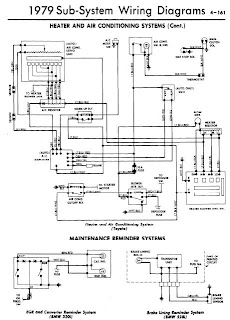
All Models 1978 Heater and Air Conditioning Systems Wiring Diagrams
Manufacturers: Toyota, BMW
Models: Corolla, 320i, 528i
Year: 1978
1 Page Wiring Diagrams
Download/Readhere
Models: Corolla, 320i, 528i
Year: 1978
1 Page Wiring Diagrams

File Size: 55 KB
File Type: PDF
Ford Sierra Escort Cosworth RS Repair Manual
Manufacturer: Ford
Model: Sierra RS Cosworth and Escort RS Cosworth
Quick Reference Index:

Download/Readhere
Model: Sierra RS Cosworth and Escort RS Cosworth
Quick Reference Index:

- Format and Usage
- Vehicle Identification
- Fuel Consumption
- Health and Safety Precautions
- Standard Practices
- Application and Use of Specifications
- Solvents and Sealers
- Road and Roller Testing
- Wheels and Tyres
- Braking System
- Power Assisted Steering
- Front Axle and Suspension
- Front Axle, Suspension and Driveshafts
- Rear Axle, Suspension and Driveshafts
- Manual Transmission and Clutch
- Engine
- Ignition System
- Cooling System
- Exhaust System
- Starting System
- Engine Management and Emission System
- Charging System
- Exterior Lights, Direction Indicators, Horn and Windscreen Wipers
- Interior Lights, Instruments, Instrument Panel Controls
- Heating and Ventilation
- Interior and Exterior Trim
- Pre Delivery and Maintenance Procedures
File Size: 28 MB
File Type: PDF
Toyota Land Cruiser 1982 Wiring Diagrams
Manufacturer: Toyota
Model: Land Cruiser
Year: 1982

Model: Land Cruiser
Year: 1982
2 Pages Wiring Diagrams
-Engine Compartment, Fuse Block and Underdash
-Intrument Panel, Underdash and Rear Compartment

File Size: 132 KB
File Type: PDF
Toyota Cressida 1981 Wiring Diagrams
Manufacturer: Toyota
Model: Cressida
Year: 1981

Download/Readhere
Model: Cressida
Year: 1981
4 Pages Wiring Diagrams
-Engine Compartment
-Underdash
-Instrument Panel and Rear Compartment

File Size: 316 KB
File Type: PDF
Toyota Corolla 1981 Wiring Diagrams
Manufacturer: Toyota
Mode: Corolla
Year: 1981

Download/Readhere
Mode: Corolla
Year: 1981
4 Pages Wiring Diagrams
-Engine Compartment and Fuse Block
-Underdash
Instrument Panel and Rear Compartmetn

File Size: 305 KB
File Type: PDF
Toyota Supra 1981 Wiring Diagrams
Manufacturer: Toyota
Model: Supra
Year: 1981

Model: Supra
Year: 1981
4 Pages Wiring Diagrams
-Engine Compartment
-Fuse Block
-Under Dash
-Instrument Panel
-Rear Compartment

File Size: 279 KB
File Type: PDF
Nissan R32 Repair manual
Manufacturer: Nissan
Model: R32
Year: 1989 - 1994
Quick Reference Index:

Download/Readhere
Model: R32
Year: 1989 - 1994
Quick Reference Index:
- General Information
- Engine
- Chassis
- Body
- Heater and Air Conditioner
- Electrical System
- Service Data
Engine Repair Index:
- How to use this manual
- General Precautions
- Vehicle and Unit Identification Plate Location
- Consult
- Tightening Torque of Standard Bolts
- Towing
- 4WD Inspection and Repair Precautions
DOWNLOAD Part 1 (main manual
DOWNLOAD Part 2 (engine manual)
File Size: 45 MB
File Type: PDF
Isuzu Trooper 1998-2002 Workshop Manual
Manufacturer: Isuzu
Model: Trooper 6VD1/6VE1, 4JG2, 4JX1
Year: 1998 - 2002
Quick Reference Index:

Download/Readhere
Model: Trooper 6VD1/6VE1, 4JG2, 4JX1
Year: 1998 - 2002
Quick Reference Index:
- General Information
- Maintenance and Lubrication
- Service Information
- Heating and Ventilation
- Air Conditioning
- Compressor Overhaul
- Front End Alignment
- Front Suspension
- Rear Suspension, Coil Spring
- Wheels and Tires
- Differential
- Driveline Control System (Shift on the Fly)
- Driveshaft System
- Transfer Case
- Brake Control System
- Anti-Lock Braking System
- Power Assisted Braking System
- Parking Brakes
- Engine Mechanical
- Engine Cooling
- Engine Fuel
- Engine Electrical
- Ignition System
- Starting and Charging System
- Engine Drivability and Emissions
- Engine Exhaust
- Engine Lubrication
- Engine Speed Control System
- Automatic Transmission
- Manual Transmission
- Clutch
- Lighting System
- Wiper/Washer System
- Entertainment System
- Wiring System
- Meter and Guage
- Body Structure
- Seats
- Security and Locks
- Sun Roof/Convertible Top
- Exterior and Interior Trim
File Size: 60 MB
File Type: PDF
Nissan 300ZX Z32 1996 Repair Manual
Manufacturer: Nissan
Model: 300ZX Z32 Series
Year: 1996
** Includes Circuit and Wiring Diagrams
 Quick Reference Index:
Model: 300ZX Z32 Series
Year: 1996
** Includes Circuit and Wiring Diagrams

- General Information
- Maintenance
- Engine Mechanical
- Engine Lubrication and Cooling System
- Engine Fuel System
- Emission Control System
- Engine Control, Fuel and Exhaust Systems
- Clutch
- Manual Transmission
- Automatic Transmission
- Propeller Shaft and Differential Carrier
- Front Axle and Front Suspension
- Rear Axle and Rear Suspension
- Brakes
- Steering System
- Body
- Heater and Air Conditioner
- Electrical System
File Size: 36 MB
File Type: RAR, DOC
Nissan S13 CA18DET Service Manual
Manufacturer: Nissan
Model: Silvia S13
Year: 1989-1994
 Quick Reference Index:
Download/Readhere
Model: Silvia S13
Year: 1989-1994

- General Information
- Maintenance
- Engine Mechanical
- Engine Lubrication and Cooling Systems
- Engine Fuel and Emission Control Systems
- Engine Control, Fuel and Exhaust Systems
- Clutch
- Manual Transmission
- Automatic Transmission
- Propeller Shaft and Differential Carrier
- Front Axle and Front Suspension
- Rear Axle and Rear Suspension
- Brake System
- Steering System
- Body
- Heater and Air Conditioner
- Electrical System
File Size: 26 MB
File Type: PDF
Audi S90 & 100 1970-73 Brake Repair Guide
Models Covered
- S90 (1970-72)
- 100 (1970-73)
DESCRIPTION
Brake system is hydraulically operated, utilizing a tandem master cylinder and Teves T 51/349 power brake unit. Front disc brakes consist of rotors attached to transmission output flanges, and two-piston calipers attached to transmission. Disc pads are equipped with a ceramic transmitter-type wear sensor. Transmitter is mounted on cross spring and will break when contact is made with pad plates, interrupting control circuit and causing indicator light on instrument panel to be activate. Rear brakes are leading-trailing shoe/drum type, using a dual piston wheel cylinder. Parking brake is cable actuated, operating secondary shoes of rear brake assemblies.
ADJUSTMENT
NOTE - Adjustments or readjustments should be carrier out on cold brakes. However, brakes must be warm when testing. Instrument panel trim must be removed to adjust master cylinder push rod free play.
MASTER CYLINDER PUSH ROD FREE PLAY
Check brake pedal free play by measuring distance between master cylinder push rod and master cylinder piston. This measurement should be .039" (1.0 mm), which would give free play of .20" (5.08 mm) at brake pedal. If necessary to adjust, loosen lock nut on push rod and turn push rod until correct clearance is obtained. Tighten lock nut and again measure pedal free play at brake pedal.
FRONT DISC BRAKES
Front disc brakes are self-adjusting, therefore, no adjustment in service is required.
REAR DRUM BRAKES
Raise and support rear of vehicle release parking brake. Using a 17 mm wrench, tighten eccentric adjusters until wheels can no longer be turned by hand. Loosen eccentric adjusters until wheels are just free to turn.
PARKING BRAKE
Raise and support rear of vehicle and adjust rear brakes. Lift parking brake lever until it engages third ratchet stop. Adjust nut at equalizer until rear wheels are just free to turn. When parking brake lever is pulled up one additional notch (to fourth ratchet stop), rear wheels should be locked.
HYDRAULIC SYSTEM BLEEDING
Fill master cylinder reservoir with brake fluid and maintain level throughout bleeding operation. Attach a hose to bleeder screw, and immerse opposite end in a container partially full of brake fluid. Open bleeder screw approximately one-half turn, depress brake pedal, close bleeder screw, and slowly return pedal. Continu operation until air bubbles are no longer seen in discharge fluid. Bleeding sequence is left-rear, right-rear, right-front, left-front.
REMOVAL & INSTALLATION
FRONT DISC BRAKE PADS
Removal - Remove lock clips. Pull out retaining pins so they project into openings in side members. NOTE - Do not remove rubber grommets from side member holes. Using a suitable extractor tool (SB-3), remove disc pads from caliper.
NOTE - Disc pads can be removed on right side only after removing front exhaust pipe.
Installation - Press both pistons into caliper bores.
NOTE - Fluid level in master cylinder reservoir will rise.
Siphon sufficient fluid to prevent reservoir from overflowing. Ensure pistons are in correct alignment in bores using suitable tool (B-5). Install disc pads in recesses of caliper, slide in retaining pins, and install lock clip. Pump brake pedal several times to position disc pads. Bleed hydraulic system if necessary.
FRONT DISC BRAKE CALIPER & ROTOR
Removal - 1) On vehicles equipped with automatic transmission, disconnect steering damper from its bracket and move out of way. On all models, depress brake pedal approximately 1.2" (30.48 mm) and hold in this position by using suitable pedal support. Disconnect temperature transmitter wire from connector (near transmission)
2) On automatic transmission equipped vehicles, disconnect hydraulic line at union on transmission, EGR line at exhaust pipe, and exhaust pipe from hangers. On all models, disconnect and remove front exhaust pipe and shield from manifold, and drive shaft at stub axle.
3) Remove ball joint mounting bolts, pull wheel downward, and swing out steering knuckle after prying it off ball joint. Remove disc brake pads, leaving spring and wire in vehicle. Remove EGR filter from oil pan. Remove caliper mounting nuts, then remove caliper and rotor from stub axle. NOTE - If necessary, pry engine assembly to one side to ease removal.
Installation - To install, reverse removal procedure, tighten caliper mounting bolts securely, and bleed hydraulic system.
REAR BRAKE DRUM
 |
| REAR BRAKE ASSEMBLY |
Removal - Raise and support vehicle, remove wheel and tire assembly. Pry off dust cap, remove cotter pin from hex nut, and remove nut. Remove brake drum making sure that retaining washer and wheel bearing do not fall out.
Installation - To install, reverse removal procedure adjust brakes, and adjust wheel bearings. See Wheel Bearing Adjustment in WHEEL ALIGNMENT Section.
REAR BRAKE SHOES
Removal - With brake drum removed, remove retaining spring for brake shoes. Remove shoes as an assembly by disconnecting spring at bottom, pulling shoes back from wheel cylinder, and disconnecting parking brake cable.
Installation - To install, reverse removal procedure and not the following: Make sure long ends of retainin clip and spring are installed on secondary shoe and parking brake lever. Ensure brake shoes are correctly positioned on wheel cylinder pistons.
REAR BRAKE WHEEL CYLINDER
Removal - With drum and shoes removed, depress brake pedal approximately 1.4" (35.56 mm) and hold in this position by using suitable pedal support. Disconnect remaining hydraulic line and cylinder mounting nuts. Separate master cylinder from power unit, taking care not to lose "O" ring installed between units.
Installation - To install, reverse removal procedure, adjust brakes and bleed hydraulic system.
MASTER CYLINDER
Removal - Disconnect hydraulic line at rear of master cylinder. Depress brake pedal 1.2-1.6" and hold in position using a suitable pedal support. Disconnect remaining hydraulic line and cylinder mounting nuts. Separate master cylinder from power unit taking care not to lose "O" ring installed between them.
Installation - To install, reverse removal procedure and bleed hydraulic system.
POWER BRAKE UNIT
Removal - Siphon brake fluid from master cylinder reservoir and disconnect hydraulic lines. Loosen hose clamp and disconnect vacuum hose from power unit. From inside vehicle, remove trim below instrument panel as necessary. Disconnect push rod form brake pedal, remove power unit adapter attaching nuts, and remove power unit and master cylinder from engine compartment as an assembly. Separate master cylinder and adaptor from power unit.
Installation - To install, reverse removal procedure and note the following: Be sure to install "O" ring between master cylinder and power unit. Install adaptor to power unit so that center punch mark on adaptor is located on lower right hand side facing engine. To complete installation, adjust pedal push rod free play and bleed hydraulic system.
Check Valve Replacement - A vacuum check valve is locate in vacuum line between intake manifold and power it. To remove, loosen hose clamps, separate vacuum hoses from check valve, and remove check valve. To install, reverse removal procedure and not the following: Check valve is stamped with the word "MOTOR" and an arrow. End of valve in which arrow points must be connect to shorter hose from intake manifold.
OVERHAUL
FRONT DISC BRAKE CALIPER
 |
| FRONT DISC BRAKE CALIPER ASSEMBLY |
Disassembly - Remove disc pads. Pry out retaining ring and remove dust seal by hand. Place a small block of wood in caliper cavity, and remove piston by applying compressed air to fluid inlet. Remove remaining piston in same manner. Remove seal from caliper bore using a piece of wood or plastic. NOTE - Do not use hard or sharp tools for this purpose. Do not separate caliper halves.
FRONT DISC BRAKE CALIPER ASSEMBLY
Cleaning & Inspection - Clean all parts in alcohol only. Check cylinder bore and piston for damage. NOTE - Do not machine caliper bore or piston. Parts are serviced by replacement only.
 |
| PINION INSTALLATION |
Reassembly - Coat all parts with ATE brake cylinder paste (or equivalent), reverse disassembly procedure, and note the following: Use new seals, dust boots, and retaining rings when reassembling. When installing piston, make sure machined surface of piston face makes a 20° angle to wall of caliper bore (see illustration). Install disc pads after caliper has been installed on vehicle.
REAR WHEEL CYLINDER
Disassembly - Thoroughly clean outside of cylinder. Remove end caps, piston and seal assemblies, and spring. Remove dust cap and bleeder screw.
 |
| AUDI MASTER CYLINDER (COMPONENT PARTS) |
Cleaning & Inspection - Clean all parts in alcohol only. Check all parts for rust, corrosion, and damage. Check cylinder bore and piston for wear or damage. Cylinder bore should not exceed .6287" (16.00 mm) and piston diameter should not be less than .619" (15.74 mm). NOTE - Manufacturer recommends replacing rubber components on each disassembly.
Reassembly - Reverse disassembly procedure and not the following: Apply a thin coat of ATE brake cylinder paste (or equivalent) to all parts during assembly.
MASTER CYLINDER

Disassembly - Remove reservoir, brake light switch, circlip and dismantle cylinder. To extract piston, unscrew stop screw.
Cleaning & Inspecting - Clean all parts in denatured alcohol. Inspect bore and piston for rust or wear and replace any parts out of tolerance. It is advisable to always replace rubber parts.
Reassembly - Preassemble pistons and coat cups with ATE brake cylinder paste (or equivalent). Insert assembly into cylinder bore, install stop screw and circlip. Install brake light switch and resrevoir.
NOTE - Models without power brake servo differ slightly. Primary piston desgin is somewhat varied. Piston is equipped with only on secondary boot. There is no air compensating bore. Brake light switch location is different.

Toyota Tercel 1981 Wiring Diagrams
Manufacturer: Toyota
Model: Tercel
Year: 1981

Model: Tercel
Year: 1981
4 Pages Wiring Diagrams
-Engine Compartment
-Fuse Block
-Under Dash
-Instrument Panel
-Rear Compartment

File Size: 222 KB
File Type: PDF
Wednesday, September 5, 2012
Audi Fox 1973-77 Brake Repair Guide
DESCRIPTION
Brake system is hydraulically operated, utilizing a tandem master cylinder and a Teves power brake unit. Front disc brakes consist of rotors attached to wheel hubs, and single piston floating caliper assemblies attached to steering knuckles. The disc brake pads are equipped with wear indicators that create a pulsation in the brake pedal when the pads are worn. Rear brakes are leading trailing shoe/drum type, using a dual piston wheel cylinder. Parking brake cable actuated, operating secondary shoes of rear brake assemblies. Pressure regulator valves for rear wheels mount to power brake unit.
ADJUSTMENT
FRONT DISC BRAKE PADS
Front disc brakes are self-adjusting, therefore, no adjustment in service is required.
REAR DRUM BRAKE SHOES
Raise and support rear of vehicle, release parking brake. Use a brake spoon, tighten rear star adjuster until wheel can no longer be turned by hand. Loosen star until wheels are just free to turn.
PARKING BRAKE
With rear brake shoes properly adjusted, pull parking brake handle to second notch. Tighten parking brake adjusting nut rear wheels can just be turned by hand, then tighten lock nut. Release handle and ensure both rear wheels rotate freely.
PRESSURE REGULATOR VALVE
Operation Test - Place hand around pressure regulator. Depress brake pedal relatively hard. Release pedal; listen and feel for a slight "knock" in each regulator. This is the piston returning in regulator.
Pressure Test - 1) Use two pressure gauges that will record at least 1400 psi. Hook one gauge to left rear wheel cylinder. Attach other gauge to right front caliper cylinder. Bleed both hoses through bleeder gauges. Operate pedal vigorously several times.
2) Depress brake pedal until gauge on right front caliper reads 497 psi at the same time the gauge hooked to the left rear wheel cylinder should read 384 psi.
3) Continue depressing pedal and hold it in position when right front gauge reads 1400 psi, left rear wheel cylinder gauge should read between 768-862 psi. Repeat procedure to check other side. Replace any regulator that does not meet specifications outlined here.
HYDRAULIC SYSTEM BLEEDING
Fill master cylinder reservoir with brake fluid and maintain level throughout bleeding operation. Attach a hose to bleeder screw, and immerse end in a container partially full of brake fluid. Open bleeder screw approximately one-half turn, depress brake pedal, close bleeder screw, and slowly return pedal. Continue operation until air bubbles are no longer seen discharged fluid. Bleeding sequence is right-rear, left-rear, right-front, left-front.
REMOVAL & INSTALLATION
FRONT DISC BRAKE PADS
Removal - Raise and support front of vehicle and remove wheel and tire assembly. Pull spring locks out of retaining pins, drive retaining pins out toward outside of vehicle, and remove cross spring. Use a suitable tool (P 86), remove inboard brake pad. Pull mounting frame and brake cylinder outwards until outboard pad can be removed
Installation - Press piston to bottom of travel in cylinder and floating frame. NOTE - Level in master cylinder reservoir will rise. Siphon off sufficient fluid to prevent overflowing. Ensure machined portion of piston face makes a 20° angle to lower caliper wall. Install disc pads by reversing removal procedure.
FRONT DISC BRAKE CALIPER
Removal - With wheel and tire assembly and disc brake pads removed, disconnect hydraulic line from caliper. Remove bolts securing caliper to steering knuckle and remove caliper.
Installation - Reverse removal procedure and bleed hydraulic system.
FRONT DISC BRAKE ROTOR
Removal - With wheel and tire assembly removed, remove caliper. NOTE - Do not disconnect hydraulic line unless necessary. Remove screw securing rotor to wheel hub and withdraw rotor.
Installation - Reverse removal procedure and bleed hydraulic system if necessary.
REAR BRAKE DRUM
Removal - Pry off grease cap. Remove cotter pin, castle nut, hex nut, and washer. Pull off brake drum making sure that inner race of outer bearing is not lost.
REAR BRAKE SHOES
 |
| Fig. 1 Exploded View of Rear Brake Assembly |
Removal - With brake drum removed, disconnect lower spring by removing from primary shoe. Remove shoe vibration cups, springs, and pins. Remove primary shoe from backing plate, disconnect parking brake cable from lever, and remove secondary shoe and parking brake lever assembly.
Installation - Reverse removal procedure and not the following: Before installing secondary brake shoe, make sure that rear wheel cylinder piston is positioned so that web face outward and opening inward. Ajust brakes and bleed hydraulic system if necessary.
REAR BRAKE WHEEL CYLINDER
Removal - Depress brake pedal approximately 1.2" to close compensator bore in master cylinder, and hold in position using a suitable pedal support. Disconnect hydraulic line from cylinder and plug with rubber cap from bleeder screw. Remove bolts attaching wheel cylinder to backing plate. Remove cylinder by maneuvering out of backing plate
Installation - Reverse removal procedure and not the following: Make sure that rear piston is installed in wheel cylinder so that web faces outward and opening inward. Bleed hydraulic system.
 |
| Fig. 2 Audi Fox Disc Brake Caliper Assembly |
MASTER CYLINDER
Removal - Siphon brake fluid from master cylinder reservoir. Disconnect hydraulic lines at cylinder, remove nuts attaching master cylinder to power unit, and remove master cylinder.
Installation - Reverse removal procedure and not the following: Make sure "O" ring is installed between master cylinder and power unit. After installing master cylinder, bleed hydraulic system.
OVERHAUL
FRONT DISC BRAKE CALIPER
Disassembly - Remove disc pads and pry mounting frame and piston assembly off floating frame. Remove brake cylinder and guide spring from floating frame. Remove clamp and dust cap from brake cylinder, then withdraw piston. NOTE -If necessary, apply compressed are to fluid inlet. Remove seal from cylinder.
Cleaning & Inspection - Thoroughly clean all parts in alcohol. Check all parts for rust, corrosion, or other damage; replace parts as necessary. NOTE - Manufacturer recommends replacing rubber parts whenever caliper has been disassembled.
Reassembly - Apply a thin coat of ATE brake cylinder paste (or equivalent) to cylinder, piston and seal, and reassemble. Place guide spring in groove of brake cylinder, then drive cylinder on floating frame with a brass mandrel. Place mounting frame in guide spring, then slide it on floating frame.
REAR BRAKE WHEEL CYLINDER
 |
| Fig. 3 Exploded View of Rear Wheel Cylinder |
Disassembly - Remove rubber dust caps, then withdraw front and rear piston and seal assemblies. Remove seals from pistons. Remove bleeder screw and dust cap.
Cleaning & Inspection - Thoroughly clean all components in alcohol. Inspect cylinder and pistons for rust, corrosion, or scoring; replace parts as necessary. NOTE - Manufacturer recommends replacing all rubber parts whenever cylinder has been disassembled.
Reassembly - Reverse disassembly procedure and note the following: Pistons are not interchangeable. Install notched piston in front of cylinder so that it will engage primary shoe when installed on backing plate.
 |
| Fig. 4 Master Cylinder Pinion Assembly |
MASTER CYLINDER

Disassembly - Remove "O" ring from master cylinder housing. Remove retaining ring and loosen piston stop screw, then remove both pistons from housing. Remove pressure valves and reservoir from master cylinder housing. Disassemble piston assemblies as necessary.
Cleaning & Inspection - Clean all parts in alcohol and check for rust, corrosion, or other damage; replace parts as necessary. Make sure compensating and filler holes are not plugged.
Reassembly - Reverse disassembly procedure and note the following: Make sure pressure and intermediate piston cups are installed correctly. See Fig. 4. Use new "O" ring on master cylinder between cylinder and power unit.
POWER BRAKE UNIT
NOTE - No information available for Overhaul of power brake unit.


Arrow & Colt 1976 Brake Repair Guide
DESCRIPTION
Brake system is hydraulically actuated, using a tandem master cylinder and on models equipped with the 2000 cc engine, a power brake unit. All models are equipped with disc brakes on the front wheels and drum brakes on the rear wheels. Front disc brakes consist of a rotor and single piston, floating caliper assembly. Rear brakes are self-adjusting, leading-trailing shoe/drum type, actuated by a dual piston wheel cylinder. Parking brake is cable actuated, operating on the rear wheel brake assemblies. All models use a combination valve to control pressure on rear wheels.
ADJUSTMENT
FRONT DISC BRAKE PADS
Front disc brakes are self-adjusting, therefore, no adjustment in service is required.
REAR BRAKE SHOES
Rear drum brakes are self-adjusting, therefore, no adjustment is necessary.
PEDAL HEIGHT AND FREE PLAY
Adjust pedal height (distance front top of brake pedal to toe board) to specifications by moving pedal stopper (stop light switch). Pedal height should be as indicated. After pedal height is adjusted, loosen push rod lock nut and adjust free play as indicated.
Pedal Height & Free Play Adjustment
Application Pedal height Fee Play
In. (mm) In. (mm)
Arrow
Power Brakes................. 6.9-7.1.............................. .4-.6
(175-180) (10-15)
Without Power Brakes.... 6.5-6.7.............................. .4-.6
(165-170) (10-16)
Colt..................................... 6.4-6.6.............................. .4-.6
(162-167) (10-15)
PARKING BRAKE
1) Release parking brake lever. Loosen cable attaching bolt and adjusting nut, and move cable lever to right. Adjust clearance of left to .04" (1.0 mm), then tighten attaching bolt. Clearance is measured between extension lever and stopper
2) With left cable adjusted, turn adjusting nut until same clearance obtained on right extension lever. With parking brake properly adjusted, lever stroke should be 4-6 notches (8-12 clicks)
COMBINATION VALVE
NOTE - Valve accomplishes three functions: Pressure control of rear service brakes; trouble warning; deactivating rear brake pressure control when front service brakes fail.
Pressure Test - Use two pressure gauges that will measure at least 1,500 psi. Hook one gauge to master cylinder rear side and one rear wheel cylinder. Pressure reading should be as shown in chart. Replace defective as required
Brake Hydraulic Pressure Chart
Application Pressure
Wheel Cylinder..................................... 460±28.4 psi
Master Cylinder.................................... 640 psi
| Fig. 1 Sectional View of Combination Valve |
Warning Light Test - Slightly loosen bleeder screw of one wheel cylinder and depress brake pedal. At this time warning light should come on. If light does'nt work, check switch and wire connector.
Combination Valve Reset - Tighten whichever bleeder screw has been opened (ie: drum wheel cylinder), then loosen the opposite system bleeder screw (ie: caliper wheel cylinder). Press brake pedal down until light goes out, close bleeder.
HYDRAULIC SYSTEM BLEEDING
Attach a bleed tube to wheel cylinder bleeder screw and immerse opposite end of tube in a container partially filled with brake fluid. Depress and release pedal several times, hold in applied position, loosen bleeder screw, allow air to escape, and tighten bleeder screw. Continue operation until air bubbles are no longer seen in discharged fluid. Repeat procedure at remaining brake lines until all air is bled from system. Bleeding sequence is right-rear, left-rear, left-front, and right-front.
REMOVAL AND INSTALLATION
FRONT DISC BRAKE PADS
| Fig. 2 Installing Spring and Clip on Brake Pads and Retaining Pins |
Removal - Raise and support vehicle and remove front wheel. Remove pad protector by prying up edge of clip of center of protector. Hold center of "M" clip, detach "M" clip from pad and its ends from retaining pins, remove clip. Remove retaining pins from caliper and remove "K" spring. Remove pads from caliper by grasping backing plate are of pads with pliers.
Installation - Press piston to bottom of bore using a suitable tool, install disc pads and retaining pins. Install "K" spring and "M" clip, making sure positions are not reversed. See illustration. Install pad protector, making sure clips face outward.
FRONT DISC BRAKE CALIPER
Removal - With disc pads removed, disconnect hydraulic line and bolts attaching caliper assembly to steering knuckle, and remove caliper assembly.
Installation - Reverse removal procedure, tighten caliper mounting bolts evenly, and bleed hydraulic system.
FRONT DISC BRAKE ROTOR
Removal - With caliper assembly removed, remove hub dust cap, cotter pin, lock nut, and adjustment nut. Pull hub and rotor assembly from spindle, taking care not to drop outer wheel bearing. Remove bolts attaching rotor to hub, then separate.
Installation - Reverse removal procedure, tighten rotor-to-hub bolts evenly, and adjust wheel bearings. See Wheel Bearing Adjustment in WHEEL ALIGNMENT Section.
REAR BRAKE SHOES
| Fig. 3 Exploded View of Arrow Rear Brake Assembly |
Removal - Raise and support vehicle and remove brake drum. Remove shoe hold-down springs. Disconnect strut-to-shoe spring and upper shoe return spring end from trailing shoe. Remove trailing shoe and lower return spring. Hold adjusting latch downward, pull adjusting lever toward center of brake, and remove leading shoe assembly. remove upper shoe return spring and strut-to-shoe spring.
Installation - Reverse removal procedure and note the following: Apply brake greas to all shoe contact points of backing plate, adjuster assembly, and wheel cylinder. Adjust amount of engagement of adjusting lever with strut only after pulling lever fully toward center of brake. Note that adjusting lever and latch spring differ between right and left sides.
REAR WHEEL CYLINDER
Removal - With rear drum and brake shoes removed, disconnect hydraulic line from wheel cylinder at rear of backing plate, remove bolts attaching cylinder and remove wheel cylinder.
Installation - Reverse removal procedure, tighten mounting bolts evenly, and bleed hydraulic system.
MASTER CYLINDER
Removal - Disconnect hydraulic lines from master cylinder, then depress brake pedal slowly several times to discharge brake fluid. On models with power brakes, remove clevis bolt retaining master push rod to brake pedal, then on all models, remove cylinder attaching bolts and lift off master cylinder.
Installation - Reverse removal procedure, check and adjust pedal height and bleed hydraulic system.
POWER BRAKE UNIT
NOTE - Before removal or overhaul test check valve. Pull of vacuum hose, place finger over check valve and crank engine; vacuum should be created.
Removal - With master cylinder removed, disconnect vacuum host from power brake unit. Remove pin connecting power unit operating rod to brake pedal, then loosen attaching nuts and remove power unit.
Installation - Reverse removal procedure and note the following: Apply a suitable sealer to power unit mounting surface and vacuum line connections. Adjust pedal height and bleed hydraulic system.
OVERHAUL
FRONT DISC CALIPER
| Fig. 4 Disassembled View of Master Cylinder |
Disassembly - Remove caliper attaching bridge bolts and separate outer and inner halves. Remove retaining ring and dust seal, apply compressed air to fluid inlet, and remove piston. Remove piston seal taking care not to damage caliper bore or seal groove.
Cleaning & Inspection - Clean all metal parts in trichloroethylene, alcohol, or brake fluid; clean piston seal in brake fluid or alcohol; clean dust seal and other rubber parts in alcohol only. Inspect caliper bore and piston for wear, damage or rust; replace parts as necessary.
NOTE - Manufacturer recommends replacing piston seal and dust seal whenever piston has been removed.
Reassembly - Reverse disassembly procedure and not the following: Apply rubber grease to piston seal and brake fluid to piston when reassembling. If torque plate was removed from inner caliper half, clean torque plate was removed from inner caliper half, clean torque plate shaft and shaft bore in caliper, then apply special rubber grease to rubber bushing, wiper seal inner surface, and torque plate shaft before reassembly. Tighten bridge bolts of caliper halves evenly.
MASTER CYLINDER
| Fig. 5 Disassembled View of Master Cylinder |
Disassembly - Remove dust boot, retaining ring, stop washer, and piston stop bolt, and withdraw primary piston assembly, secondary piston assembly, and secondary return spring from master cylinder. NOTE - Do not disassembly primary piston assembly. Remove check valve caps, tube seats, check valves, and check valve spring.
Inspection - Check master cylinder bore and piston for wear or other damage and replace as necessary. Check clearance between cylinder bore and piston; if clearance exceeds .006", replace parts are necessary. Check all parts of secondary piston assembly; if any parts are found defective, replace complete secondary piston assembly.
Reassembly - Reverse disassembly procedure and note the following: Apply rubber grease to all parts (except boots) before reassembly. When assembled, check that return part is not blocked by piston cup when piston is located at return position.
POWER BRAKE UNIT
Disassembly - 1) Hold front shell flange (master cylinder end of power unit) in a vice and remove clevis and lock nut. Scribe alignment mark on front and rear shells for reassembly reference. Holding neck of rear shell on both sides with pipes, remove rear shell by turning it counterclockwise. NOTE - diaphragm spring can be removed at the same time. Remove diaphragm plate assembly from rear shell.
| Fig. 6 Lubricate at Points Indicated |
2) Using suitable driver, remove rear shell retainer and lift out bearing and valve body seal. Pull diaphragm from diaphragm plate assembly, then using a screwdriver, remove silencer and filter. Hold valve plunger, with key hole facing down and remove stop key by lightly pushing valve rod while shaking unit, then remove valve rod and plunger assembly. Remove reaction disc. NOTE - Valve rod plunger assembly can not be disassembled. Remove flange from shell, then pull off plate seal assembly.
Cleaning & Inspection - Thoroughly clean and dry each part. NOTE - Cups and plastic parts must be wiped off only. Inspect diaphragm plate for damage and cracks. NOTE - Diaphragm plate is made of plastic and should be handled carefully at all times. Check push rod for damage and straightness. Check font and rear shells for cracks, damage and deformation. Repair or replace any defective part.
| Fig. 7 Locations for Measuring Master Cylinder Push Rod-to-Piston Clearance |
Reassembly - 1) Apply a sufficient amount of silicone grease to the following parts (see illustration): Front shell seal and push rod sliding surfaces (A); push rod and seal contact surfaces (B); diaphragm lug-to-rear shell contacting surface (C); outside surface of reaction disc (D); reaction disc inserting part of diaphragm plate (E); rear shell seal and diaphragm plate sliding surfaces (F); interior of piston plate into which plunger assembly is inserted and seal sliding surfaces (G).
2) Install seal and bearing into rear shell, then press in retainer. Gently install valve rod and plunger, then install stop key witch chamfered end toward piston side. NOTE - After installing stop key, pull plunger assembly to ensure plunger is securely locked by stop key. Install reaction disc and diaphragm in diaphragm plate assembly, then install silencer filter and silencer into rear of diaphragm plate and press in retainer.
Volvo 240 260 Series 1975-77 Drive Axles Repair Guide
Models Covered
- 240 Series
- 260 Series
DESCRIPTION
Rear axle assembly uses a hypoid type ring gear and pinion gear set. Semi-floating axle shafts are retained in housing by tapered roller bearings and a bearing retainer at housing outer ends. Bearing clearance is not adjustable and is determined by bearing design. Differential adjustment is accomplished by the use of shims.
AXLE RATIO & IDENTIFICATION
A plate attached on left side of axle housing gives axle ratio part number, and serial number.
REMOVAL & INSTALLATION
AXLE SHAFT & BEARINGS
1) With vehicle raised and wheels removed, disconnect brake line from caliper. Remove disc and caliper. Loosen bolts for thrust washer through holes in axle flange. Pull out shaft using suitable puller. Remove inner sealing ring using a puller or by prying it out with a screwdriver.
2) Press bearing and lock ring off axle shaft using suitable tools. Remove oil seal. Fill space between new seal lips with grease, then install seal on axle shaft. Install bearing and new lock ring by pressing on axle shaft. Always use a new lock ring and insure that bearing is installed with taper away from axle shaft flange.
3) Use a suitable seal installing tool and install inner seal ring. Fill bearing with good quality grease. Also fill space between seals and between seal lips with grease. Install axle shaft and tighten thrust washer bolts. Install brake disc and caliper, reconnect brake line, bleed and adjust brakes. Install road wheels and lower vehicle
PINION FLANGE & SEAL
1) Disconnect rear section of propeller shaft from pinion flange. Check for looseness of pinion in its bearing. If it is loose, this must be remedied before a new oil seal is installed. Remove nut from flange using suitable flange using suitable flange holding tool. Pull off flange using suitable puller. Pull out old oil seal.
2) Coat seal lip of new ring with grease. Also lubricate the spring coil so it does not jump off during installation. Install oil seal using suitable seal installing tool. Press on flange using suitable pressing tool. Install flange washer and nut and tighten. Reconnect propeller shaft.
AXLE ASSEMBLY
1) With rear of vehicle raised and supported and wheels removed, support rear axle with suitable jack and holding fixture. Remove upper attaching bolts for shock absorber and parking brake cables from levers and brackets on brake backing plate. Remove propeller shaft from pinion flange and remove pipe union from rear axle housing.
2) Disconnect Panhard rod from bracket on rear axle housing and remove lower attaching bolts for spring. Lower jack until trailing arms release from spring. Loosen bolts holding rear axle housing to trailing arms. Lower jack and pull rear axle assembly forward.
3) To install, move axle under vehicle and install bolts for support arms and torque rod. Raise jack until Panhard rod can be installed. Install attaching bolts for spring and tighten nuts for support rods and trailing arms. Install bracket, union, and brake hoses. Reconnect propeller shaft to pinion flange. Install upper bolt for shock absorbers and reconnect parking brake cable. Adjust parking brake and bleed brakes. Install wheels and lower vehicle
OVERHAUL
DISASSEMBLY
1) Place axle assembly in suitable holding fixture with pinion flange pointing downward. Remove brake lines and axle shafts. Remove inspection cover. If final drive is being reconditioned because of noise, run a tooth contact pattern check before disassembly as this may assist in locating fault.
2) Check alignment marking on bearing caps and carrier. If there are no marking, or if they are difficult to see, mark one side with a punch. Remove cap. Using a suitable case stretching tool, lift out carrier with ring gear. Turn final drive over and drain oil. Remove pinion flange and press out pinion. Remove pinion front bearing washer and oil seal with a suitable driver.
3) If necessary, drive out rear pinion bearing from case using a suitable drift. Clean axle case gasket surface and remove any burrs present. If necessary, pull of rear bearing from pinion using a suitable puller. Pull off differential carrier bearing with suuitable puller and retain shims. Remove lock plate for ring gear bolts, remove bolts and ring gear. Drive out lock pin securing differential gear and remove shaft, gears and thrust washers.
 |
| Fig. 1 Exploded View of Volvo Drive Axle Assembly |
INSPECTION
 |
| Fig. 2 Pinion Adjusting Ring & Tool |
Inspect all parts for wear or damage. Also install differential gear into carrier together with shaft and thrust washers. Use no lubricant. Now, check play of differential side gears. If play exceeds specifications when gears have been rotated to maximum play, replace thrust washers with thicker ones.
REASSEMBLY & ADJUSTMENT
Case Assembly - Place differential side gears together with thrust washers in differential carrier. "Roll" in both side pinions simultaneously with dished thrust washers, then drive in shaft. Install ring gear, making sure that contact surfaces are clean and without any burrs. Install new ring gear bolts and tighten.
 |
| Fig. 3 Measuring Drive Pinion Gear Installed Height |
Drive Pinion Depth & Bearing Preload - 1) Clean marking surface on drive pinion. Install adjusting ring tool (2685) and (2841) on pinion and place this assembly into housing. Place pinion on carrier so bolt on adjusting ring faces large side of carrier.
2) The pinion should have a certain nominal measurement to the center line of the ring gear. Due to manufacturing tolerances, there are deviations from this nominal measurement. On rear axles made by Volvo, the deviation is always positive and is indicated hundredths of a millimeter. The plus sign is excluded.
3) Place pinion gauge (2393) on ground surface of pinion and adjusting jig (2393) in differential bearing positions. Place dial indicator retainer (2284) with dial indicator on gasket face of axle housing with dial indicator foot touching adjusting ring. Zero dial indicator. Now move indicator over until it touches pinion gauge. If the pinion is, for example, marked 33, the pinion gauge should lie .013" (.33 mm) under adjusting fixture. The setting is adjusted by turning cam on pinion until dial indicator shows correct value, then lock adjusting ring with set screw.
 |
| Fig. 4 Zeroing Dial Indicator |
4) Remove measuring tool and pinion. Place complete rear pinion bearing with outer ring in measuring fixture (tool 2600). Put on plate, spring and nut with flat side of nut facing up. Rotate plate and bearing several times so that rollers take up correct set. Place adjusting ring in retainer (tool 2284) and dial indicator opposite adjusting ring, zero indicator. Set pointer of indicator to outer ring of bearing. The indicator will now show directly the thickness the shims should have. Measure shims for correct thickness with micrometer. Since it is unlikely to find a shim with the exact thickness required, shim may be .0012" (.03 mm) thicker or .002" (.05 mm) thinner than measured value.
5) Press rear bearing on pinion with suitable sleeve. The washer under rear bearing inner ring must NOT be installed when overhauling. Place measured shims in axle housing and press in both outer rings of bearings using suitable tool. Insert pinion in housing and install three .03" (.75 mm) thick shims and front pinion bearing. Pull pinion into housing using suitable tool. Install washer and nut on pinion shaft and tighten to specifications.
 |
| Fig. 5 Measuring Installed Depth of Pinion Gear |
6) Install pinion gauge and dial indicator retainer. Pull down pinion while rotating it backwards and forwards. Set dial indicator to zero. Press pinion upwards while rotating it forwards and backwards. Dial indicator will read clearance.Remove pinion and remove shims corresponding to the measured clearance plus .003" (.07 mm). Reinstall pinion. Now use torque gauge to check pinion bearing torque. Adjust shim thickness if required to obtain specified torque. Recheck pinion depth using measuring tools as described in step 3.
Backlash & Side Bearing Preload - 1) Lubricate inside of adjustment rings (tool 2595) and install then on differential carrier. Ring with block oxidized adjustment ring should be placed on ring gear side. Also lubricate bearing bores in carrier. Install carrier and adjustment rings in axle housing.
2) Use dial indicator and adjust ring so that specified backlash is obtained. Backlash may vary within backlash range but get as closer to specified backlash as possible.
| Fig. 6 Determining Pinion Depth Shim Thickness |
NOTE - Due to altered manufacturing and test procedures, it is no longer possible to determine correct installation of gears by means of a contact pattern test. The pinion gear should always be installed in its marked position regardless of the contact pattern.
3) If the gear set is correctly installed, but still causes noise, try re-positioning the pinion gear .002 (.05 mm) plus or minus (try plus first). This may help if the pinion gear has been incorrectly marked.
4) After correct backlash is obtained, remove carrier and adjustment ring. Place adjusting ring and bearing into measurement fixture with flat side of nut facing downwards. Rotate plate several times. Install dial indicator and retainer tool (tool 2284) and zero indicator on adjusting ring. Place measuring point of indicator facing bearing and read off indicator.
5) Use a micrometer to form a shim pack equal in thickness to clearance indicated by dial indicator plus .003" (.07 mm). Place shims together with measured bearing to one side. Repeat this procedure with the other bearing. Install shims on differential carrier, making sure which side respective bearing and shims are installed on, and press on bearings using suitable drift. When installing second bearing, use suitable support so as not to damage first bearing.

NOTE - Do not forget to lock cover for ring gear bolt.
6) Install tool (2394) on pinion carrier and expand tool until pins are flush against hole edges in carrier, then tighten screws an additional 3 1/2 turns. Install differential carrier and outer rings. Install bearings caps and tighten bolts to specification.
7) Install pinion oil seal and flange, and inspection cover and gasket. If inner oil seals for axle shafts were removed, drive them in with suitable tool. Reinstall axle shafts and adjust end play if necessary. install brake discs, caliper and brake pipes. Bleed and adjust brakes.
Subscribe to:
Posts (Atom)