Monday, February 6, 2012
Volvo 1974 Wheel Alignment Guide
TIRE INFLATION (COLD)
Before attempting to check or adjust wheel alignment, make sure tires are properly inflated. Refer to manufacturer's specifications given in owner's manual.CASTER
All Models - If caster is not within specifications, loosen bolts at upper control arm shaft using suitable tool (SVO 2713). Increase caster angle by adding shims at rear bolt or by removing shims from front bolt. To decrease caster angle, remove shims at front bolt or add shims to rear bolt. Tighten bolts and recheck caster angle.
CAMBER
All Models - If camber is not within specifications, loosen bolts at upper control arm using suitable tool (SVO 2713). To increase camber angle, remove equal amount of shims from front and rear bolts. To decrease camber angle, add shims to front and rear bolts in equal amounts. Tighten bolts and recheck camber angle.
TOE-IN
All Models - Place wheels in straight-ahead position and loosen lock nuts on steering links (tie-rods). To adjust toe-in, rotate adjustable sleeves until correct toe-in is obtained. Tighten lock nuts and recheck toe-in.


Volvo 1963-73 Wheel Alignment Guide
1963-73 VOLVO SPECIFICATIONS AND ADJUSTMENTS
TIRE INFLATION (COLD)
Before attempting to check or adjust wheel alignment, ensure that tires are properly inflated.
CASTER
Model 544 - If caster is not within specifications, loosen clamp bolt securing eccentric bushing located on upper control arm. Using suitable tool (SVO 1411 or SVO 2201) turn the eccentric bushing. One complete turn alters caster by 1/2 degrees.
NOTE - If camber is correct, one complete turn of eccentric must be completed to eliminate camber change. Tighten clamp bolt and recheck caster.
160 Series and 140 Series - If caster not within specifications, loosen bolts at upper wishbone shaft using suitable tool (SVO 2713). Increase caster by adding shims at rear bolt or by removing shims from front bolt. To decrease caster, remove shims at front bolt or add to rear bolt. Tighten bolts and recheck caster.
P1800 Series - Check caster and camber. If caster is not within specifications and camber is correct, adjust caster as follows.
Raise vehicle and support under body at jacking points. Loosen front axle member attaching bolts. To correct caster, add or remove shims between front axle member and side member. Some amount of change must be done on both sides of vehicle to avoid undue strain on front axle member. Tighten bolts and recheck camber.
If caster is not within specifications and camber is incorrect adjust caster as follows:
Bend up locking plate for bolts at upper control arm shaft and loosen bolts. Increase caster by adding shims to rear bolt or by removing shims from front bolt. To decrease caster, remove shims from rear bolt or add to front bolt. Tighten bolts and recheck caster. If caster is within specifications, lock bolts with locking plate.
CAMBER
Model 544 - If camber is not within specifications, loosen clamp bolt securing eccentric bushing located on upper control arm. Using suitable tool (SVO 1411 or SVO 2201) turn the eccentric bushing to change camber. NOTE - Altering camber also means a slight alteration of caster, but amount of negligible. Tighten clamp bolt and recheck camber.160 Series & 140 Series - If camber is not within specifications, loosen bolts at upper wishbone shaft using suitable tool (SVO 2713). To increase camber, remove equal amounts of shims from front and rear bolt. To decrease camber, add shims to front and rear bolt in equal amounts. Tighten bolts and recheck camber.
P1800 Series - If camber is not within specifications, bend up locking plate and loosen bolts at upper control arm shaft. To increase camber, decrease amount of shims and add shims to decrease camber. Shims of same thickness must be added or removed to both attaching bolts or caster will be affected.
NOTE - On 1972-73 models, total thickness of shims at each bolt may not exceed .48" (12.2 mm) and difference in thickness between shims at front and rear may not exceed 0.1" (2.54 mm). Tighten bolts and recheck camber. If camber is within specifications, lock bolts with locking plate.
TOE-IN
All Models (1963-73) - Place wheels in straight ahead position and loosen lock nuts (late models) or clamping bolts (early models) on tie rod. To adjust toe-in to specifications, rotate tie rod. Tighten lock nuts or clamping bolts and recheck toe-in.
Friday, February 3, 2012
Volkswagen 1976 Wheel Alignment Guide
ADJUSTMENT
TIRE INFLATION (COLD)
Before attempting to check or adjust wheel alignment, make sure tires are properly inflated. Refer to manufacturers specifications given in owner's manual.CASTER
Caster angle is part of front axle design and is not adjustable. If not within specifications, inspect front suspension for wear or damage and replace or repair components as necessary.CAMBER
Type 1 and 2 (Front) - Camber is adjusted by an eccentric bushing. Loosen nut on upper torsion arm, then rotate eccentric bushing until specified camber angle is obtained. NOTE - Basic setting is with eccentric notch facing in forward position. Adjustment must be made within 90 degrees either direction.Dasher (Front) - If adjustment is necessary, loosen nuts at attaching ball joint to track control arm. To adjust, insert suitable adjusting tool (40-200) in adjusting holes in control arm and pry ball joint sideways until camber is set to specifications. NOTE - Difference in camber between wheels should not vary more than 1 degrees. Tighten attaching nuts and recheck camber.
NOTE - On dasher models, insert tool from on right side and from rear on left side.
Rabbit and Scirocco (Front) - If adjustment is necessary, loosen nuts of suspension strut-to-wheel bearing housing mounting bolts. Turn eccentric bolt (upper mounting bolt) until specified camber angle is obtained. Tighten mounting bolt nuts and recheck camber angle.
Type 1 (Rear) - Camber angle is dependent on torsion bar adjustment. If camber angle is not within specifications, see Torsion Bar Adjustment.
Type 2 (Rear) - If minor adjustment is necessary, loosen bolts attaching bearing housing to spring plate and diagonal arm. Adjust by changing position of bearing housing in elongated holes in spring plate. Tighten bolts and recheck camber. NOTE - Range that this procedure will cover is very small.
Dasher, Rabbit and Scirocco (Rear) - Rear camber is not adjustable. If camber angle is not to specifications, inspect rear suspension for wear or damage and repair or replace components as necessary.
TOE-IN
Type 1 ( Front) - Working on inner end of tie rod, bend up lockplate. Loosen lock nut and clamp bolts from tie rods. Top tapered rings from inn er end of right side tie rod. Rotate tops of tie rods. Forward rotation increases toe-in; rearward rotation decreases toe-in. When specified to is achieved, placte tie rods so ball joints are not angled. Tighten clamp bolts and lock nuts. If steering wheel is centered after making adjustment, use Fig. 1 to recenter steering wheel. NOTE - Centering steering wheel will not alter toe-in |
| Fig. 1 Direction of Tie Rod Rotation to Align Steering Wheel (Type 1 Only) |
Type2 (Front) - 1) Right side tie rod adjust front wheel toe. Press drag link off steering drop arm. Place left side wheel in straight-ahead position. Adjust right side tie rod until specified to is obtained.
2) Place steering gear so protrusion on dust cap is properly aligned. Attach drag link to drop arm. Drag link must enter mounting with no tension against it. Readjust drag link if necessary.
Dasher, Rabbit, Scirocco (Front) - Place front wheels in straight-ahead position. Loosen lock nut on adjustable tie rod end (left side, Dasher; right side, Rabbit and Scirocco). Hold axle boot to avoid twisting. Adjust right side tie rod until specified toe-in.
Type 1 (Rear) - If adjustment is necessary, remove nuts securing spring plate but do not remove bolts. To adjust, move diagonal arm forward or backward in slotted spring plate mounting holes.until toe-in is set to specifications. Install spring plate attaching nuts and recheck toe-in.
Type 2 (Rear) - If adjustment is necessary, loosen bolts attaching bearing housing to spring plate and diagonal arm. Change position of bearing housing in elongated holes on spring plate. Tighten bolts and recheck toe-in.
All Other Models (Rear) - Toe-in is not adjustable. If toe-in is not within specifications, inspect rear suspension for wear or damage and repair or replace components as necessary.
TORSION BAR ADJUSTMENT (REAR)
Type 1 - Using a suitable protractor, find deviation of vehicle from horizontal plane and note reading which will be used in setting angle of spring plate. Install spring plate on torsion bar and measure position with protractor. If not within specifications, adjust by moving torsion bar, one spline at a time, forward or backward until correct position is obtained.Type 2 - Using a suitable protractor, check horizontal position of vehicle on one frame side member. Reading should be noted; it will be used in setting spring plate angle. Insert inner end of torsion bar in center anchor and pres spring plate on outer end of torsion bar. Adjust protractor on unloaded spring plate until bubble is in center position. Adjust torsion bar one spline forward or rearward until correct specifications are obtained.

Tuesday, January 31, 2012
Volkswagen 1973 Models Wheel Alignment Guide
1973 VOLKSWAGEN SPECIFICATIONS AND ADJUSTMENTS
TIRE INFLATION (COLD)
Before attempting to check or adjust wheel alignment, make sure tires are properly inflated. Refer to manufacturers specifications given in owner's manual.CASTER
Caster angle is part of front axle design and is not adjustable. If not within specifications, inspect fornt suspension for wear or damage and repair or replace components as necessary.CAMBER
All Models Excluding Super Beetle and Type 4 (Front) - If adjustment is necessary, loosen hex nut on upper ball joint. Using suitable tool (VW 179), adjust eccentric bushing until correct camber angle is obtained. Tighten hex nut.Super Beetle (Front) - If adjustment is necessary, loosen nut (max. one turns) on control arm bolt and turn bolt until correct camber angle is obtained. Tighten nut.
Type 4 (Front) - If adjustment is necessary, raise vehicle and loosen front carrier mounting bolts. Move carrier sideways until correct camber angle is obtained. NOTE - Vehicle must be level (laterally) on lift. If not, compensate fore lateral angle. Tighten front axle carrier bolts and lower vehicle.
All Models Excluding Type 4 (Rear) - Camber angle is dependent upon torsion bar adjustment. If camber angle is not within specifications, See Torsion Bar Adjustment.
Type 4 (Rear) - Loosen lower control arm brackets and turn on longitudinal axis. If outer bracket is lowered and inner bracket is raiised, camber angle will increase. If moved in opposite direction, camber will decrease. Adjust camber angle to specifications and tighten lower control arm brackets.
TOE-IN
Type 1 Excluding Super Beetle (Front) - With front wheel in straight-ahead position, loosen clamps on steering links (tie-rods). Turn both steering link clamps equally until correct toe-in is obtained. Tighten clamps.Super Beetle (Front) - If adjustment is necessary, position front wheels in straight-ahead position. Loosen steering link (tie-rod) clamps and turn clamps equally to obtain correct toe-in. Tighten clamps.
Type 1 and 3 (Rear) - If adjustment is necessary, loosen bottom axle tube flange. Using suitable tool (VW 160) set toe-in to specifications. NOTE - Relieve tension on tool before taking reading. Tighten bolts.
Type 4 (Rear) - If adjustment is necessary, use suitable tool (VW 361/1) and set toe-in to specifications by turning eccentric bolts on inner arm brackets.
TORSION BAR ADJUSTMENT (REAR)
Type 2 and 3 - Using suitable protractor (VW 261) find deviation of vehicle from horizontal plane and not reading, which will be used in setting angle of spring plate. Install spring plate on torsion bar and measure position (using protractor for VW 261). If not within specifications, adjust by moving torsion bar spline forward or backward until correct position is obtained.Type 2 - Using suitable protractor (VW 245A) check horizontal position of vehicle on one frame side member. Reading should be noted since it will be used in setting spring plate angle. Insert inner end of torsion bar. Adjust protractor on unloaded spring plate until bubble is in center position. Adjust torsion bar one spline forward or rearward until correct specifications are obtained.
1973 Models


1974 Models


Volkswagen 1962-72 Models Wheel Alignment Guide
1962-72 VOLKSWAGEN SPECIFICATIONS AND ADJUSTMENTS
TIRE INFLATION (COLD)
Before attempting to check or adjust wheel alignment, ensure that tires are properly inflated.
CASTER
All Models - The caster angle is part of the front axle design and is non-adjustable. If not within specifications, check for worn or damaged parts as necessary.CAMBER
Type 1 (1962-65) & Type 2 (1962-68) - Camber is non adjustable. If alignment is not within specifications, check for damaged or worn parts and replace as necessary.Type 1 Excluding Super Beetle (1966-72), Type 3 (All) & Type 2 (1969-72) - Loosen hexagon nut on upper ball joint and turn eccentric bush with suitable tool (VW 179) until camber within specifications. Tighten hexagon nut.
Sedan 113 Super Beetle (1971-72) - Adjust camber by loosening nut (max 1 turn) on control bolt and turn bolt to set camber angle to specifications. Tighten nut.
Model 411 (1971-72) - To adjust, raise vehicle just off floor on hoist and loosen front carrier mounting bolts. Move carrier sideways until camber angle is within specifications on both sides. NOTE - Vehicle must be level laterally on lift. If not, lateral angle must be accounted for. Tighten front axle carrier bolts and lower vehicle.
All Models Rear (Exc. 411) - Camber angle is dependent upon torsion bar and spring plate setting. If camber not within specifications, See Torsion Bar Adjustment.
Model 411 Rear (1971-72) - Loosen wishbone brackets and turn on longitudinal axis. If outer bracket is lowered and inner bracket raised, camber angle will increase. If moved in opposite direction, camber will decrease. Adjust camber to specifications and tighten wishbone brackets.
TOE-IN
Type 1 Excluding Super Beetle (1962-72) - Position front wheels to center position and loosen hexagon nuts and clamp (if present) on tie rods. Turn both tie rods in the same direction by equal amounts to adjust toe-in to specifications. Tilt both tie rods in the same direction to align tie rods. Tighten hexagon nuts and clamps.Sedan 113 Super Beetle (1971-72) - Using suitable tool (113 415 375), align steering to center position. Loosen clamp nut and lock nut on tie rods. Turn tie rods until each wheel is set to 1/2 the total toe angle. Align tie rods by tilting ends as far as they will go and tighten lock nut and clamp nut. Remove centering tool.
Type 2 (1962-72) & Type 3 (1965-72) - Position front wheels to center position and loosen lock nuts at both ends of the adjustable tie rod. Turn tie rod to adjust toe-in to correct specifications. Tighten lock nuts.
Model 411 (1971-72) - Use suitable tool (VW 279a) to align steering to center position. Loosen clamping bolts and nuts on both tie rods. Adjust toe-in to specifications by turning both tie rods (equal amounts) in same direction. Align tie rods with each other by tilting the tie rod. Tighten clamps and nuts.
Type 1 Rear (1962-68) & Type 3 Rear (1965-68) - To adjust, loosen the bolts in axle tube flanges, hook in suitable tool (VW 147) and set toe to specifications. NOTE - On Type 1 vehicles with equalizer spring, the guides for the push rods must be removed when checking the toe. Release tension on tool before taking reading. Tighten bolts in axle tube flanges.
Type 1 Rear (All 1969-72) and Type 3 Rear (1969-72) - Loosen spring plate bolts. Using suitable tools (VW160 and VW179) set toe angle on both sides to specifications. Tighten spring plate bolts.
Type 2 Rear (1962-68) - Toe angle is dependent upon torsion bar and spring plate setting. If toe angle not within specifications, See Torsion Bar Adjustment.
Type 2 Rear (1969-72) - To adjust toe angle, loosen bolts in the axle tube flange. Using suitable tool (VW 160) set toe to correct specifications. Relieve tension on tool before taking reading. Tighten bolts.
Model 411 Rear (1971-72) - Using suitable aligning tool (VW 361/1) adjust toe angle to specifications. Turn the eccentric bolts in the brackets for the inner arms of the wishbone to change toe angle.
TORSION BAR ADJUSTMENT
All Models Rear Excluding Model 411 & Type 2 (1962-68) - Using suitable protractor (VW 261) find deviation of vehicle from the horizontal and note reading to be taken into account in setting spring plate angle. Install spring plate on torsion bar and measure position using protractor (VW 261). If not within torsion bar specifications adjust by moving torsion bar one spline forward and spring plate back on spline or torsion bar back one spline and spring plate forward one spline until readings are within specifications.Type 2 Rear (1972-68) - Using suitable protractor (VW 245a) check horzontal position of vehicle on one of frame side members. Reading to be taken into account in setting spring plate angle. Insert inner end of torsion bar in center angchor and press spring plate on outer end of torsion bar. Adjust protractor (VW 245a) on the unloaded spring plate until bubble is in center position. Adjust to specifications by moving torsion bar one spline forward and spring plate back on spline or torsion bar back one spline and spring plate forward one spline until readings are within specifications.


Volkswagen 1965 Models Wheel Alignment Guide
ADJUSTMENT
TIRE INFLATION (COLD)
Before attempting to check or adjust wheel alignment, make sure tires are properly inflate. Refer to manufacturers specifications given in owner's manual.CASTER
Caster angle is part of front axle design and is not adjustable. If not within specifications, inspect front suspension for wear or damage and repair or replace components as necessary.CAMBER
Type 1 and 2 (Front) - Camber is adjusted by an eccentric bushing. Loosen nut on upper torsion arm, then rotate eccentric bushing until specified camber angle is obtained. NOTE - Basic setting is with eccentric notch facing in forward position. Adjustment must be made within 90 degrees either direction.Dasher (Front) - If adjustment is necessary, loosen nuts at touching ball joint to track control arm. To adjust, insert suitable adjusting tool (40-200) in adjusting holes in control arm and pry ball joint sideways until camber is set to specifications. NOTE - Difference in camber between wheels should not vary more than 1 degrees. Tighten attaching nuts and recheck camber
NOTE - On Dasher models, insert tool from front on right side and from rear on left side.
Rabbit and Scirocco (Front) - If adjustment is necessary, loosen nuts of suspension strut-to-wheel bearing housing mounting bolts. Turn eccentric bolt (upper mounting bolt) until specified camber angle is obtained. Tighten mounting bolt nuts and recheck camber angle.
Type 1 (Rear) - Camber angle is dependent on torsion bar adjustment. If camber angle is not within specifications, see Torsion Bar Adjustment.
Type 2 (Rear) - If minor adjustment is necessary, loosen bolts attaching bearing housing to spring plate and diagonal arm. Adjust by changing position of bearing housing in elongated holes in spring plate. Tighten bolts and recheck camber. NOTE - Range that this procedure will cover is very small.
Dasher, Rabbit and Scirocco (Rear) - Rear camber is not adjustable. If camber angle is not to specifications, inspect rear suspension for wear or damage and repair or replace components as necessary.
TOE-IN
Type 1 (Front) - Working on inner end of right tie rod, bend up lockplate. Loosen lock nut and clamp bolts from tie rods. Top tapered rings from inner end of right side tie rod. Rotate tops of tie rods. Forward rotation increases toe-in; rearward rotation decreases toe-in. When specified toe is achieved, place tie rods so ball joints are not angled. Tighten clamp bolts and lock nuts. If steering wheel is not centered other making adjustment, use Fig. 1 to recenter steering wheel. NOTE - Centering steering wheel will not alter toe-in.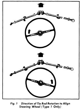
Type 2 (Front) - 1) Right side tie rod adjust front wheel toe. Press drag link off steering drop arm. Place side wheel in straight-ahead position. Adjust right side tie rod until specified toe is obtained.
2) Place steering gear so protrusion on dust cap is properly aligned. Attach drag link to drop arm. Drag link must enter mounting with no tension against it. Readjust drag link if necessary.
Dasher, Rabbit, Scirocco (Front) - Place front wheels in straight-ahead position. Loosen lock nut an adjustable tie rod end (left side, Dasher; right side. Rabbit and Scirocco). Hold axle boot to avoid twisting. Adjust right side tie rod until specified toe-in is obtained. Tighten lock nut and recheck toe-in.
Type 1 (Rear) - If adjustment is necessary, remove nuts securing spring plate but do not remove bolts. To adjust, move diagonal arm forward or backward in slotted spring plate mounting holes until toe-in is set to specifications. Install spring plate attaching nuts and recheck toe-in.
Type 2 (Rear) - If adjustment is necessary, loosen bolts attaching bearing housing to spring plate and diagonal arm. Change position of bearing housing in enlongated holes on spring plate. Tighten bolts and recheck toe-in.
All Other Models (Rear) - Toe-in is not adjustable. If toe-in is not within specifications, inspect rear suspension for wear or damage and repair or replace components as necessary.
TORSION BAR ADJUSTMENT (REAR)
Type 1 - Using a suitable protractor, find deviation of vehicle from horizontal plate and note reading which will be used in setting angle of spring plate. Install spring plate on torsion bar and measure position with protractor. If not within specifications, adjust by moving torsion bar, one spline at a time, forward or backward until correct position is obtained.Type 2 - Using a suitable protractor, check horizontal position of vehicle on one frame side member. Reading should be noted; it will be used in setting spring plate angle. Insert inner end of torsion bar in center anchor and press spring plate on outer end of torsion bar. Adjust protractor on unloaded spirng plate until bubble is in center position. Adjust torsion bar one spline forward or rearward until correct specifications are obtained.

Genera Wheel Alignment Troubleshooting Guide
WHEEL ALIGNMENT TROUBLESHOOTING
NOTE - This is a general trouble shooting guide. When using this guide, locate the condition in column one that corresponds your problem and determine the possible causes in column two. Match the number of the possible cause with the same number in column three, and you will have the suggested correction.
| CONDITION | POSSIBLE CAUSE | CORRECTION |
| Tire Wear | 1) Tire pressure too low 2) Wheel alignment out of tolerance. 3)Excessively worn wheel bearings. 4)Improper or no tire rotation | 1) Check manufacturer's recommended pressure and set to specifications. 2) Check alignment and set to specifications. 3) Check, adjust or replace bearings. 4) Follow manufacturer's recommended procedures, Perform a 4 or 5 tire rotation. |
| Getting tire noise | 1) Improper tire pressure 2) Wheel alignment out of tolerance. 3) Damaged or defective spindle or suspension components. | 1) Check manufacture's recommended pressure and set to specifications. 2) Reset alignment or replace necessary suspension components. 3) Inspect and replace components. |
| Uneven tire wear | 1) Uneven tire pressure 2) Tire pressure too low (shoulders on tire worn) 3) Tire pressure too high (center of tred worn) 4) Bent rotor or wheel 5) One side of front tred worn 6) Inside of tred worn 7) Outside of tred worn 8) Excessive wheel bearing play 9) Brake operation on only one side | 1) Check manufacturer's recommended pressure and set to specifications 2) See correction 1 3) See correction 1 4) Check and replace part 5) Inadequate camber 6) Inadequate toe-in 7) Excessive toe-in 8) Inspect and adjust bearings 9) Check and adjust brakes |
| Road noise | 1) Abnormal tire wear 2) Tire out of balance 3) Tire pressure too low | 1) Replace tire 2) Rebalance tire 3) Check manufacturer's recommended pressure and set to specifications. |
Subscribe to:
Posts (Atom)