Thursday, December 15, 2011
1973-74 Jensen-Healey Wheel Alignment Guide
JENSEN-HEALEY SPECIFICATIONS AND ADJUSTMENTS
Before attempting to check or adjust wheel alignment, make sure tires are properly inflated. Refer to manufacturers specifications given in owner's manual.
CASTER
If caster angle is not to specifications, adjust length of strut rods by loosening both (front and rear) lock nuts. Caster angle is decreased by shortening rods and increased by lengthening rods.
CAMBER
Camber angle is not adjustable. If not to specifications, check suspension for wear or damage and replace components as necessary
TOE-IN
Measure difference of distance between front of front tires and rear of front tires. If not to specifications, adjust by loosening outer sterring links and adjusting both equally to obtain specifications.
 |
| 1973 Wheel Alignment Specifications |
 |
| 1974 Wheel Alignment Specifications |
Monday, December 12, 2011
Honda Confirms NSX Concept
Good news to our NSX fans! The rumors are over the place and Honda confirms that they're building a new concept NSX car and it'll be unveiled on Detroit Auto Show on January 9, 2012.
On topgear.com ....
 |
| The Next Honda NSX Concept Car? |
On topgear.com ....
Yoshikazu Kigoshi told Top Gear that the company "needs a halo car", a decision that has come straight down from Honda president Takanobu Ito. "A new S2000 is a difficult car for us to do," Kigoshi-san told us, "because of its front-engined rear-drive platform. But we are definitely looking at the EV-ster and a new NSX."Not much detail on this car, but surely it will have a Mid-engine and it will get the company's new SH-AWD torque vectoring system, that uses independent electric motors on the rear wheels to optimise cornering behaviour. The production car will not come soon but it will surely after few years...
Thursday, December 8, 2011
1974 Jaguar Wheel Alignment Guide
JAGUAR SPECIFICATIONS AND ADJUSTMENTS
TIRE INFLATION (COLD)
Before attempting to check or adjust wheel alignment, make sure tires are properly inflated. Refer to owner's manual for manufacturer's specifications.
RIDING HEIGHT
XJ6 & XJ12 (Front) - Check that vehicle is full of gasoline oil and water, and that tires are properly inflated. Press down on front bumper and slowly release, then lift up on bumper and slowly release, this will settle front suspension. Measure distance between center of headlight and ground on both sides of vehicle. Correct height should be 24.6" (611 mm) minimum. To adjust, install or remove spring spacers from front coil spring. NOTE - Spring spacers are 1/8" (3.2 mm) thick, and will change riding height approximately 5/16" (7.9 mm).
XKE V-12 (Front) - Check that vehicle is full of gasoline, oil, and water and that tires are properly inflated. Roll vehicle forward three car lengths to settle suspension system. Measure distance from lower front sub-frame to ground on each side of vehicle. This measurement should be 6 1/4±1/4". If necessary to adjust, loosen lock nut on cam adjuster of lower control arm. Rotate cam adjuster to give correct height. Tighten locknut and recheck riding height.
All Models (Rear) - Check that vehicle is full of gasoline water and oil, and that tires are properly inflated. Roll forward three car lengths to settle suspension system. Measure distance between lower surface of rear crossmember and ground on both sides of vehicle. Correct height should be 7.45±.25" (189±6mm) on XJ6 and XJ12 models or 7.9±.25" (201±6 mm) on XKE V-12. If height is incorrect, it will be necessary to replace all four rear springs.
 |
| Caster and Camber Setting Tool (XJ6 & XJ12) |
PREPARATION FOR CASTER AND CAMBER ADJUSTMENT (XJ6 & XJ12)
Ensure vehicle is on level ground and that tires are properly inflated. Before checking or adjusting caster or camber it will be necessary to fabricate two setting tools (see illustrations). Compress front suspension and insert tools under upper control arms adjacent to control arm rubber stops and over brackets welded to bottom of control arms. Compress rear suspension and install suitable suspension setting links (J.25), to lock rear suspension in place (see illustration). Vehicle is now locked in half-loaded condition and caster and camber can be checked and adjusted.
 |
| LOCKING REAR SUSPENSION (All Models) |
CASTER
NOTE - Before adjusting caster angle, make sure car is standing at normal riding height.
XJ6 and XJ12 - If caster angle is not within specifications, adjust by moving shims on front and rear of upper control arm ball joint. To increase caster, loosen bolts securing upper ball joint and move shims from rear of ball joint to front of ball joint. To decrease caster, reverse procedure. Tighten ball joint attaching bolts and recheck caster angle
XKE V-12 - Before attempting to check or adjust caster angle, it will be necessary to simulate a half-loaded condition. This is accomplished by use of wooden blocks 6.25" high placed under caster of front sub-frame lower crossmember.. Load vehicle until crossmember contact wooden block. If caste ris not to specifications, adjust by rotating threaded shaft of upper control arm. With lock nuts loose and control arm bushing brackets loosened on sub-frame, rotate threaded shaft clockwise to decrease caster or counterclockwise to increae caster. Tighten shaft lock nuts and bolts on control arm bushing brackets.
CAMBER
NOTE - Before attempting to check or adjust camber angle it will be necessary to make sure that vehicle is standing at normal riding height.
XJ6 & XJ12 (Front) - With wheels in straight-ahead position, measure camber angle. NOTE - Two front wheels must be within 1/4 degrees of each other. Adjustment is accomplished by means of shims placed between control arm mounting bracket and the frame. Adding shims decreases camber angle. NOTE - Be sure to use the same number of shims on each bolt otherwise castor angle will be affected.
XKE V-12 (Front) - Before attempting to check or adjust camber angle, it will be necessary to simulate a half-loaded condition. This is accomplished by use of wooden blocks 6.25" high. Place wooden blocks under center of front sub-frame and load vehicle until sub-frame touches wooden blocks. If camber is not to specifications, adjust be adding or subtracting shims between upper control arm shaft and sub-frame. Shims are available in several thicknesses. The addition of one 1/16" shim will change camber angle 1/4 degrees.
All Models (Rear) - Before checking rear wheel camber, rear suspension must be in the half-loaded position. See Preparation for Caster and Camber Adjustment. To adjust, remove suspension setting links (JD.25), raise and support rear of vehicle and remove wheels. Loosen nuts securing half-shaft to brake disc, then add or remove shims as required to bring camber angle within specifications. NOTE - Addition of one .020" (5 mm) shim will alter camber 1/4 Degrees. Retighten nuts and bolts and check camber angle.
TOE-IN
All Models - Place wheels in straight ahead position and measure toe-in. If not to specifications, adjust by loosening steering link lock nuts and rotating adjuster sleeves to obtaining correct toe-in. Tighten lock nuts and recheck toe-in.

1973 Jaguar Wheel Alignment Guide
1973 JAGUAR SPECIFICATIONS AND ADJUSTMENTS
Before attempting to check or adjust wheel alignment, make sure tires are properly inflated. Refer to owner's manual for manufacturer's specifications.
RIDING HEIGHT
XJ6 (Front) - Vehicle should be loaded with sufficient weight to equal driver, three passengers and ten gallons of gasoline, or 850 lbs.
XJ6 (Rear) - Set rear riding height using two setting links (Churchill No. J25). Hook link into lower hole of rear mounting and depress body until end of tool can be slid over the hub carrier fulcrum nut.
XJ12 (Front) - With vehicle full of gasoline, water and oil, press downward on front bumper and release. Measure distance from lower (front) crossmember to ground. Make this measurement at both left and right sides of flat surface on crossmember. Now pull upward on front bumper and slowly release. Again measure distance. Calculate the average riding height for each side. This measurement should be 6 3/4 ± 1/8". If necessary to adjust, install or remove spring spacer from front coil springs.
XJ12 (Rear) - Check contents of each fuel tank and use appropriate weights to compensate for unequal weight distribution. Roll vehicle forward three car lengths, to level suspension. Measure distance between lower surface of rear crossmember and ground at both sides of vehicle. This distance should be 7.45±25". If dimension is incorrect, it will be necessary to change all four rear springs.
 |
| Jaguar Suspension Setting Links |
XKE V-12 (Front) - Check that vehicle is full of gasoline oil, and water and that tires are properly inflated. Roll vehicle forward three car lengths to settle suspension system. Measure distance from lower front sub-frame to ground on each side of vehicle. This measurement should be 6 1/4±1/4". If necessary to adjust, loosen locknut on cam adjuster of lower control arm. Rotate cam adjuster to give correct height. Tighten locknut and recheck riding height.
XKE V-12 (Rear) - Check contents of each fuel tank and use appropriate weights to compensate for unequal weight distribution. Roll vehicle forward three car lengths to settle suspension system. Measure distance between lower surface of rear crossmember and ground on both sides of vehicle. This measurement should be 7.9±.25". If dimension is incorrect, it will be necessary to change all four rear springs
CASTER
NOTE - Before adjusting caster angle, make sure car is standing at normal riding height.
XJ6 - If caster angle is not to specifications, adjust by moving shims on front and rear of upper control arm ball joint. To increase positive caster, loosen bolts securing upper ball joint and move shims from rear of ball joint to front of ball joint. To decrease caster, reverse the procedure. NOTE - There must always be at least four shims (total for front and rear) used at one time. More may be used if necessary, but never less than four.
XJ12 - Before attempting to check or adjust caster angle, it will be necessary to place enough weight in vehicle to simulate a half-loaded condition (approx. 425 lbs.). If caster angle is not to specifications, adjust by moving shims on front and rear of upper control arm ball joint. To increase positive caster, loosen bolts securing upper ball joint and move shims from rear of ball joint to front of ball joint. To decrease caster, reverse the procedure.
XKE V-12 - Before attempting to check or adjust caster angle, it will be necessary to simulate a half-loaded condition. This is accomplished by use of wooden blocks 6.25" high placed under center of front sub-frame lower crossmember. Load vehicle until crossmember contacts wooden block. If caster is not to specifications, adjust by rotating threaded shaft of upper control arm. With lock nuts loose and control arm bushing brackets loosened on sub-frame, rotate threaded shaft clockwise to decrease caster or counterclockwise to increaes caster. Tighten shaft lock nuts and bolts on control arm bushing brackets.
CAMBER
NOTE - Before attempting to check or adjust camber angle it will be necessary to make sure that vehicle is standing at normal height.
XJ6 & XJ12 (Front) - With wheels in straight ahead position, measure camber angle. NOTE - Two front wheels must be within 1/4 degrees of each other. Adjustment is accomplished by means of shims placed between control arm mounting bracket and the frame. Adding shims decreases camber angle. Be sure to use the same number of shims on each bolt otherwise caster angle will be effected.
XKE V-12 (Front) - Before attempting to check or adjust camber angle, it will be necessary to simulate a half-loaded condition. This is accomplished by use of wooden blocks 6.25" high. Place wooden blocks under center of front sub-frame and load vehicle until sub-frame touches wooden blocks. If camber is not to specifications, adjust by adding or subtracting shims between upper control arm shaft and sub-frame. Shims are available in several thicknesses. The addition of one 1/16" shim will change camber angle 1/4 degrees.
All Models (Rear) - Before attempting to check or adjust camber angle, it will be necessary to place enough weight in vehicle to simulate a half-loaded condition (approx. 425 lbs.). If camber angle is not to specifications, adjust by adding or subtracting shims between the half-shaft and brake disc. Shims are available in .020", which will alter camber angle 1/4 degrees.
TOE-IN
All Models - Place wheels in straight ahead position and measure toe-in. If not to specifications, adjust by loosening stering link lock nuts and rotating adjuster sleeves to obtain correct toe-in. Tighten lock nuts and recheck toe-in.

Monday, December 5, 2011
1962-72 Jaguar Wheel Alignment
1962-72 JAGUAR SPECIFICATIONS AND ADJUSTMENTS
TIRE INFLATION (COLD)Before attempting to check or adjust wheel alignment, ensure tires are properly inflated.

RIDING HEIGHT
Mk II, 3.8 and Mk 10 Front - Vehicle should be in unloaded condition with full tank of gas.
Mk II Rear - Vehicle should be in unloaded condition with full tank of gas.
 |
| FRONT SUSPENSION SETTING LINKS |
3.8, 420 Series, Mk 10, XKE 3.8, XKE 4.2 AND XJ6 Rear - Set rear riding height using two setting links (Churchill No. J25). Hook link into lower hole of rear mounting and depress the body until other end of tool can be slid over hub carrier fulcrum nut.
420 and 420 G Front - Place block (3 3/8" high) between upper wishbone (adjacent to bump stop rebound rubber) and bracket welded to bottom of turret. Load vehicle until wishbone is resting on block.
XJ6 Front - Vehicle should be loaded with weights equivalent to four persons and have a full tank of gas.
XKE III V12 Front - With full tanks of gas in vehicle, set block (6.125" high) under center of front sub-frame lower crossmember. Load vehicle with weights until crossmember contacts block.
XKE III V12 Rear - Measure distance between lower surface of rear crossmember and ground. If not within specifications (7.90" ± .25"), check all bushings and bearing points of rear suspension. If not defects discovered, replace rear road spring.
XKE 3. AND XKE 4.2 Front - Set links which fit over the top and bottom shock absorber mountings to hold vehicle in mid-ladden condition (see illustration for link dimensions).
CASTER
Mk II, Mk 10, 420 Series and XJ6 - If caster is not within specifications, loosen bolts securing upper wishbone member. To adjust, shims are located at upper wishbone ball joint. To increase caster, move shims from the rear side to front side of wishbone member. To decrease, move shims from front to rear. NOTE - A total of 8 shims must be used at all time exc. XJ6 which has total of 4 shims. Tighten bolts and recheck caster angle.
XKE III V12, XKE 3.8 & XKE 4.2 - If caster is not within specifications, loosen lock nuts on fulcrum shaft and wishbone clamping bolts. Rotate fulcrum shaft until caster is within specifications. Tighten wishbone clamping bolts. Remove test block and load to allow full weight of vehicle to rest on front suspension. Tighten fulcrum shaft lock nuts. NOTE - Undue torsional loading of rubber bushings will occur if weight of torsional loading of rubber bushings will occur if weight of vehicle is not on front suspension. Recheck caster.
CAMBER
Mk II, 420 Series, 3.8 Mk 10 and XJ6 Front - If camber is not within specifications, support lower wishbone at outer mounting point and remove bolts securing upper wishbone bracket. To increase camber, remove equal amount of shims from front and rear bolts. To decrease camber, add equal amount of shims to both bolts. Install and tighten bolts. Remove support and check camber angle. NOTE - Always change shims in equal amount so caster will not be affected.
XKE III V12, XKE 3.8 & XKE 4.2 Front - If camber is not within specifications, loosen bolts securing front and rear fulcrum shaft mounting brackets to sub-frame. To increase camber, add shims in equal amounts to front and rear mounting brackets. To decrease, remove shims in equal amounts. Tighten bolts and recheck camber angle.
All Models Rear (Exc. XKE III V12) - If rear camber is not within specifications, raise vehicle and remove wheel. Remove nut and washer securing forward road spring and shock absorber to wishbone mounting pin. Drift mounting pin through wishbone until assembly is free from pin. Remove nut and bolt securing top of road spring and shock absorber to cross beam and remove assembly. Loosen nuts securing half shaft to brake disc and pull hub and half shaft away from shims enough to clear disc mounting stud. Remove or ad shims as necessary to adjust camber to specifications. Reverse removal procedure and recheck camber.
XKE III V12 Rear - If rear camber is not within specifications, raise vehicle, remove wheel and use stands to support body. Remove lower wishbone outer fulcrum grease nipple. Remove nuts securing half shaft to brake disc and separate half shaft from disk. Add or remove shims to set camber to specifications. Reverse removal procedure and recheck camber angle.
TOE-IN
Mk II, 3.8 and 420 Series (Standard Steering) - Place front wheels in straight ahead position and check toe-in measurement. Move vehicle ahead so front wheels rotate 180 Degrees and take second reading. Take average of two readings to determine toe-in. If not within specifications, loosen clamp bolt at each end of center tie rod. Rotate rod, setting toe-in to specifications. Tighten clamp bolts and recheck toe-in.
XJ6 MK 10, XKE III V12, 420 Series (Power Steering) and XKE 3.8 & 4.2 - Place front wheels in straight ahead position and check toe-in measurement. Move vehicle ahead so front wheels rotate 180 degrees and take second reading. Take average of two readings to determine toe-in. If not within specifications, loosen lock nuts on side tie rod. To adjust toe-in, turn side tie rods by equal amounts to set toe-in to specifications. Tighten lock nuts and recheck toe-in

1976 Fiat Honda Jaguar Wheel Alignment Guide
FIAT
Model X1/9 Front and Rear - Camber is nonadjustable. If not within specifications, inspect suspension for damage and repair or replace parts as necessary.TOE-IN
Model 128, 131 and X1/9 Front - Place front wheels in straight-ahead position. If toe-in is not within specifications, loosen sleeve locking nut on tie rods. To adjust, rotate hexagon on ball pin to set toe-in to specifications. Hold hexagon in position and lock nut against tie rod sleeve.
Model 128 Rear - If rear toe-in is not within specifications raise rear of vehicle and compress one end of leaf spring, shifting it from flexible guide anchoring spring to control arm. Remove guide and slowly release spring. Remove nuts attaching pivot to body and loosen screws to free adjustment shims. To increase toe-in, add shims to rear screw or remove shims from front screw. To decrease, add shims to front screw or remove shims from rear screw.
Model 124 Front - Place front wheels in straight-ahead position. If toe-in is not within specifications, loosen four clamps securing sleeves on tie rods. Rotate tie rods in opposite direction (by equal amounts) to set toe-in to specifications. Tighten clamp nuts. NOTE - Expansion slot in sleeve must coincide with clamp joint when clamp is fully tightened.
Model X1/9 Rear - If rear wheel toe-in is not within specifications, loosen clamps securing sleeves to reaction rods. Adjust toe-in by lengthening or shortening reaction rods. Tighten clamps and recheck toe-in.
HONDA
ADJUSTMENTTIRE INFLATION (COLD)
Before checking or adjusting wheel alignment, make sure tires are correctly inflated. Refer to manufacturers specifications located in glove box.
RIDING HEIGHT
Make sure tires are properly inflated. Measure from bottom of side marker lamps to ground. If height measurement is not within specifications, check rear height before attempting to repair front suspension

CASTER
Caster is nonadjustable. If alignment is not within specifications, inspect for damaged parts and replace as necessary.
CAMBER
Camber is nonadjustable. If alignment is not within specifications, inspect for damaged parts and replace as necessary.
TOE-OUT
Front, CVCC and Accord - Loosen lock nuts at each end of tie rods. Turn tie rod until toe-out is within specifications. Use same procedure for both sides. To center steering wheel after toe has been adjusted, turn both tie rods in same direction til steering wheel (spokes) are centered. Tighten lock nuts.
TOE-IN
Rear, CVCC and Accord - To adjust toe-in, loosen nuts on radius rods. Rotate radius rods until toe-in is within specifications, then tighten lock nuts. NOTE - Each notch on cam plate is equal to 5/64" movement.
JAGUAR
ADJUSTMENTSTIRE INFLATION (COLD)
Before attempting to check or adjust wheel alignment, make sure tires are properly inflated. Refer to owner's manual for manufacturer's specifications.
RIDING HEIGHT
All Models (Front) - 1) Check that vehicle is full of fuel, oil and water, and that tires are properly inflated. Press down on front bumper and slowly release, then lift up on bumper and slowly release, this will settle front suspension.
2) On XJ6 and XJ12 models, measure distance between center of outer headlight and ground on both sides of vehicle. Height should be 24.6" (611 mm) minimum.
3) On XJS models, measure distance between lower face of crossmember and ground on both sides. Height should be 6.0" (152 mm) minimum, plus thickness of slip plates.
4) On all models, adjust by installing or removing spring spacers from front coil spring. NOTE - Spring spacers are 1/8" (3.2 mm) thick and will change riding height approximately 5/16" (7.9 mm).
All Models (Rear) - Check that vehicle is full of gasoline, water and oil, and that tires are properly inflated. Roll vehicle forward three car lengths to settle suspension system. Measure distance between lower surface of rear crossmember and ground on both sides of vehicle. Correct height should be 7.45±.25 (189±6 mm). If height is correct, it will be unnecessary to proceed further, however if height is incorrect, all four rear springs will need to be replaced.
 |
| Fig. 1 Dimensions for Fabricating the Two Necessary Setting Tools |
PREPARATION FOR CASTER AND CAMBER ADJUSTMENT
1) Ensure vehicle is on level ground and that tires are properly inflated. Before checking or adjusting caster or camber it will be necessary to fabricate two setting tools (See Fig. 1.)
2) Compress front suspension and insert tools under upper control arms, adjacent to control arm rubber stops and over brackets welded to bottom of control arms.
3) Compress rear suspension and install suitable suspension setting links (J.25), to lock rear suspension in place (See. Fig. 2). Vehicle is now locked in half-loaded condition and caster and camber can be checked and adjusted.
 |
| Rear Suspension in Locked Position with Special Tool |
CASTER
NOTE - Before adjusting caster angle, make sure car is standing at normal riding height.
All Models - If caster angle is not within specifications , adjust by moving shims on front and rear of upper control arm ball joint. To increase caster, loosen bolts securing upper ball joint and move shims from rear of ball joint to front of ball joint. To decrease caster, reverse procedure. Tighten ball joint attaching bolts and recheck caster angle
CAMBER
NOTE - Before attempting to check or adjust camber angle will be necessary to make sure that vehicle is in half-loaded condition
All Models (Front) - With wheels in straight-ahead position measure camber angle. NOTE - Two front wheels must be within 1/4 degrees of each other. Adjustment is accomplished by means of shims placed between control arm mounting bracket and the frame. Adding shims increases camber angle NOTE - Be sure to use the same number of shims on each bolt, otherwise caster angle will be affected.
All Models (Rear) - Before checking rear wheel camber, rear suspension must be in the half-loaded position. See Preparation for Caster and Camber Adjustment. To adjust, remove suspension setting links (JD.25), raise and support rear of vehicle and remove wheels. Loosen nuts securing half-shaft to brake disc, then add or remove shims as required to bring camber angle within specifications. NOTE - Addition of one .020" (5 mm) shim will alter camber 1/4 degrees. Retighten nuts and bolts and check camber angle.
TOE-IN
All Models - Place vehicle in straight-ahead position. Remove greae nipple from rack adjuster nut. Put centralizing tool 12279 (or equivalent) into locating hole. Push tool on to back of rack bar. Slowly turn steering wheel until tool drops into back of rack bar. Measure toe-in. If toe-in is now within specifications, adjust by loosening steering link lock nuts and rotating adjuster sleeves equal amounts, as necessary. Tighten lock nuts and recheck to-in
LUV
TIRE INFLATIONBefore checking or adjusting wheel alignment, ensure tires are correctly inflated. Refer to manufacturers specifications located in glove box or on right hand door jam.
RIDING HEIGHT
1) Place vehicle on smooth level surface. Bounce vehicle several times. Raise vehicle and allow to settle at normal height. Measure distance as shown in Fig. 1 and 2

NOTE - Height check should be made with a full tank of gas, spare tire installed, and jack included. No passengers should be in vehicle.
2) Difference between measurements of each side must not be more than 1/2". If an adjustment is necessary, it can be made at bolt on height control arm.
Riding Height Specifications
Front= 4.6" Rear = 6.0"
CASTER
Adjustmen is made with shims inserted between upper control arm pivot shaft and frame. Adding or subtracting shims from either front or rear bolts will effect a change in caster. Shims may be transferred from front to rear or from rear to front. Transfer of one shim from front bolt to rear bolt will decrease positive caster. For correct specifications, refer to table.
CAMBER
Camber is adjusted by adding or subtracting shims. Adding equal number of shims at both front and rear of pivot shaft will decrease positive camber. For correct specifications, refer to table.
TOE-IN
NOTE - Toe-in must be adjusted after caster and camber adjustment.
Toe in can be adjusted by rotating the intermediate rod after loosening lock nuts. Rotating intermediate rod towards front of vehicle reduces toe-in and towards rear of vehicle increases toe-in. For correct specifications, refer to specifications table.
Saturday, December 3, 2011
1975 Honda Wheel Alignment Guide
HONDA SPECIFICATIONS AND ADJUSTMENTS
Before checking or adjusting wheel alignment, make sure tires are correctly inflated. Refer to manufacturers specifications located in glove box
RIDING HEIGHT
Make sure tires are properly inflated. Measure from bottom of side marker lamps to ground. If height measurement is not within specifications, check rear height before attempting to repair front suspension
CASTER
Caster is nonadjustable. If alignment is not within specifications, inspect for damaged parts and replace as necessary.
CAMBER
Camber is nonadjustable. If alignment is not within specifications, inspect for damaged parts and replace as necessary.
TOE-IN
Front - To adjust toe-in, loosen lock nuts at each of the tie rods. To increase toe-in, turn the right tie rod in the direction of wheel rotations when the vehicle moves forward and turn left tie rod in the opposite direction. Turn both tie rods an equal amount until toe-in is within specifications. Tighten lock nuts of each tie rod.
Rear (CVCC Only) - To adjust toe-in, loosen lock nuts on radius rods. Rotate radius rods until toe-in is within specifications, then tighten lock nuts.

1974 Honda Wheel Alignment Guide
HONDA SPECIFICATIONS AND ADJUSTMENTS
TIRE INFLATION (COLD)
Before checking or adjusting wheel alignment, make sure tires are correctly inflated. Refer to manufacturers specifications located in glove box.
RIDING HEIGHT
Make sure tires are properly inflated. Measure from bottom side marker lamps to ground. This distance should be 25.78" in front and 24.01" in rear. NOTE - If height measurement is not within specifications, check rear height before attempting to repair front suspension.
CASTER
Caster is nonadjustable. If alignment is not within specifications, inspect for damaged parts and replace as necessary.
CAMBER
Camber is nonadjustable. If alignment is not within specifications, inspect for damaged parts and replace as necessary.
TOE-IN
To adjust toe-in, loosen lock nuts at each of the tie rods. To increase toe-in, turn the right tie rod in the direction of wheel rotation when the car4 moves forward and turn the left tie rod in the opposite direction. Turn both tie rods an equal amount until toe-in is within specifications. Tighten lock nuts of each tie rod.

Wednesday, November 30, 2011
1975 Fiat Wheel Alignment Guide
FIAT SPECIFICATIONS AND ADJUSTMENT
Before attempting to check or adjust wheel alignment, make sure tires are properly inflated. Refer to manufacturers specifications given in owner's manual.
CASTER
Model 131 and 128 (Except. Sport L) - If caster is not to specifications, raise front of vehicle. Remove stabilizer bar-to-control arm nut and disconnect control arm from body. Remove end of stabilizer bar from control arm. To adjust caster, addition of shims between end of stabilizer bar and rubber pad of control arm will decrease caster angle and removal of shims will increase caster angle. Reverse removal procedure and recheck caster.
Model 128 Sport L - If caster is not to specifications, adjust by adding or removing shims located between stabilizer bar bushing and frame.
Model 124 - If caster is not within specifications, raise front of vehicle and remove wheel and shock absorber. Using suitable tool (A.74174), compress spring to relieve lower control arm and loosen nuts holding control arm pivot bar to crossmember. To adjust caster, remove shims from front stud and move to rear stud to increase caster. To decrease caster, remove shims from rear stud and move shims to front stud. Reverse removal procedure and check caster.
Model X1/9 - If caster is not to specifications, adjust by adding or removing shims located between stabilizer bar and stabilizer bar support.
CAMBER
Model 124 - If camber is not within specifications, adjust by changing shims. Raise front of vehicle, remove wheel and shock absorber. Using suitable tool (A.74174), compress spring to relieve lower control arm and loosen nuts holding control arm pivot bar to crossmember. To increase camber, remove equal amount of shims from both studs and add equal amount of shims to decrease camber. NOTE - Adding or removing equal amounts of shims will not affect caster. Reverse removal procedure and check camber.
Model 128 and 131 Front - Camber is nonadjustable. If not within specifications, inspect suspension for damage and repair or replace parts as necessary.
Model 128 Rear - If rear camber is not within specifications raise rear of vehicle and compress one end of leaf spring, shifting it from flexible guide anchoring spring to control arm. Remove guide and slowly release spring. Remove nuts attaching pivot to body and loosen screw to free adjustment shims. To increase camber, add an equal number of shims on both screws attaching control arm to body. To decrease, remove equal number of shims from both screws. Reverse removal procedure and check camber.
Model X1/9 Front and Rear - Camber is nonadjustable. If not within specifications, inspect suspension for damage and repair or replace parts as necessary.
TOE-IN
Model 128, 131 and X1/9 Front - Place front wheels in straight-ahead position. If toe-in is not within specifications, loosen sleeve locking nut on tie rods. To adjust, rotate hexagon on ball pin to set toe-in specifications. Hold hexagon in position and lock nut against tie rod sleeve.
Model 128 Rear - If rear toe-in is not within specifications raise rear of vehicle and compress one end of leaf spring, shifting it from flexible guide anchoring spring to control arm. Remove guide and slowly release spring. Remove nuts attaching pivot to body and loosen screws to free adjustment shims. To increase to-in, add shims to rear screw or remove shims front front screw. To decrease, add shims to front screw or re3move shims from rear screw.
Model 124 Front - Place front wheels in straight-ahead position. If toe-in is not within specifications, loosen four clamps securing sleeves on tie rods. Rotate tie rods in opposite direction (by equal amounts) to set toe-in to specifications. Tighten clamp nuts. NOTE - Expansion slot in sleeve must coincide with clamp joint when clamp is fully tightened.
Model X1/9 Rear - If rear toe-in is not within specifications, loosen clamps securing sleeves to reaction rods. Adjust toe-in by lengthening or shortening reaction rods. Tighten clamps and recheck toe-in.

1963-73 Fiat Models Wheel Alignment Guide
1963-73 FIAT SPECIFICATIONS AND ADJUSTMENTS
TIRE INFLATION (COLD)
Before attempting to check or adjust wheel alignment, ensure that tires are inflated according to specifications

CASTER
Model 128 - If caster is not within specifications, raise front of vehicle. Remove anti-roll bar to control arm nut and disconnect control arm from body. Remove end of anti-roll bar from control arm. To adjust caster, addition of shims between end of anti-roll bar and rubber pad of control arm will decrease caster and removal of shims will increase caster. Reverse removal procedure and check caster.
Model 124 - If caster is not within specifications, raise front of vehicle and remove wheel and shock absorber. Using suitable tool (A.741174), compress spring to relieve lower control arm and loosen nuts holding control arm pivot bar to crossmember. To adjust caster, remove shims from front stud and move to rear stud to increase caster. To decrease caster, remove shims from rear stud and move shims to front stud. Reverse removal procedure and check caster.
Models 600D, 850 and 1100R - If caster is not within specifications, loosen two nuts on control arm pivot bar to body. To adjust, remove shims from rear stud and place shims at front stud to increase caster. To decrease caster, move shims from front stud to rear stud. Tighten nuts and check caster.
Model 1500 - No adjustment procedure available.
CAMBER
Model 124 - If camber is not within specifications, adjust by changing shims. Riase front of vehicle, remove wheel and shock absorber. Using suitable tool (A.74174), compress spring to relieve lower control arm and loosen nuts holding control arm pivot bar to crossmember. To increase camber, remove equal amount of shims from both studs and add equal amount of shims to decrease camber. NOTE - Adding or removing equal amounts of shims will not affect caster. Reverse removal procedure and check camber.
Model 1500 - No adjustment procedure available at time of this publication. See Wheel Alignment specifications.

Model 128 - Front - Camber is nonadjustable. If not within specifications, inspect suspension for damage. Repair or replace parts as necessary.
Model 128 Rear - If rear camber is not within specifications raise rear of vehicle and compress one end of leaf spring, shifting it from flexible guide anchoring spring to control arm. Remove guide and slowly release spring. Remove nuts attaching pivot to body and loosen screw to free adjustment shims. To increase camber, add an equal number of shims on both screws attaching control arm to body. To decrease, remove equal number of shims from both screws. Reverse removal procedure and check camber.
Models 600D, 850 and 1100R Front - If camber is not within specifications, adjust by changing shims. Loosen two nuts on control arm pivot bar to body. To increase camber, add equal amounts of shims to both studs and to decrease, remove equal amounts of shims. Tighten nuts and check camber.
TOE-IN
Model 128 Front - Place front wheels in straight-ahead position. If toe-in is not within specifications, loosen sleeve locking nut on tie rods. To adjust, rotate hexagon on ball pin to set toe-in specifications. Hold hexagon in position and lock nuts against tie rod sleeve.
Model 128 Rear - If rear toe-in is not within specifications raise rear of vehicle and compress one end of leaf spring, shifting it from flexible guide anchoring spring to control arm. Remove guide and slowly release spring. Remove nuts attaching pivot to body and loosen screws to free adjustment shims. To increase toe-in, add shims to rear screw or remove shims from front screw. To decrease, add shims to front screw or remove shims from rear screw.
All Other Models Front - Place front wheels in straight ahead position. If toe-in is not within specifications, loosen four clamps securing sleeves on tie rods. Rotate tie rods in opposite direction (by equal amounts) to set toe-in to specifications. Tighten clamps. NOTE - Expansion slot in sleeve must coincide with clamp joint when clamp is fully tightened.
Model 600D and 850 Rear - If rear is not within specifications, loosen screws securing lower control arm support to body. Elongated holes on support allow movement to set toe-in to specifications. Tighten screws 29-36 ft lbs. and check toe-in.
Tuesday, November 29, 2011
1974-75 Nissan Datsun Wheel Alignment Guide
DATSUN SPECIFICATIONS AND ADJUSTMENTS
TIRE INFLATION (COLD)
Before attempting to check or adjust wheel alignment, make sure that tires are properly inflated. Refer to manufacturer's specifications given in owner's manual.
RIDING HEIGHT
Pickup Only - Measure distance from center of lower control arm bushing (where it connects to body) and lower steering knuckle bushing (see illustration). To adjust, raise vehicle to release tension on anchor bolt adjusting nut and turn anchor bolt to adjust to specified height.
Riding Height Specifications
Application Inches (mm)
620 Pickup................................ 3.1-3.2 (72-82)
CASTER
All Models Exc. Pickup - Preset at factory and cannot be adjusted. If not to specifications, check suspension for wear or damage and repair or replace components as necessary.
Pickup - Caste is adjusted by increasing or decreasing thickness of shims inserted between upper link spindle and upper link mounting bracket. When front shim thickness increases, caster decreases. NOTE - Do not adjust caster with difference between front and rear shim thicknesses beyond .078" (2mm).
CAMBER
All Models (Exc. Pickup) - Preset at factory and cannot be adjusted. If not to specifications, check suspension for wear or damage and repair or replace components as necessary.
Pickup - Camber is adjusted bye increasing or decreasing the thickness of shims inserted between upper link spindle and upper link mounting bracket. When thickness of shims increase, camber decreases.
TOE-IN
All Models - Adjust by loosening each side steering link lock nut and adjusting steering link to change toe-in.
NOTE - Left and right side steering links should be adjusted equally. Tighten lock nuts.
1974 Datsun Models

1975 Nissan Datsun

1962-72 Nissan Datsun Wheel Alignment Guide
1962-72 DATSUN SPECIFICATIONS AND ADJUSTMENTS
TIRE INFLATION (COLD)Before attempting to check or adjust wheel alignment, ensure that tires are properly inflated.

RIDING HEIGHT
Pickups Only - Adjust to specificied distance by turning anchor bolt adjusting nut. Raise vehicle to release tension on adjusting nut.
 |
| Riding Height Measuring Point |
CASTER
All Models (Except 240Z, 510 and 1200) - Caster is adjusted by increasing or decreasing the thickness of shims inserted between upper link spindle and upper link mounting bracket. When front shim thickness increases, caster reduces. Set caster to specifications given in table. NOTE - Do not adjust caster with difference between front and rear shim thicknesses beyond .078".
240Z, 510 and 1200 - Caster is not adjustable. If alignment is not within specifications, check for damaged parts and replace as necessary
CAMBER
All Models (Except 240Z, 510 and 1200) - Camber is adjusted by increasing or decreasing the thickness of shim inserted between upper link spindle and upper link mounting bracket. When thickness of shims increases, camber reduces. Set camber to specifications given in table.
240Z, 510 and 1200 (Front) - Camber is not adjustable. If alignment is not within specifications, check for damaged parts and replace as necessary.
240Z and 510 (Rear) - Camber is not adjustable. If alignment is not within specifications, check for damaged parts and replace as necessary.
TOE-IN
All Models (Except Pickups) - Adjust by loosening side rod lock nuts and adjusting length of side rod to change toe-in to correct specifications. NOTE - Left and right side rods should be moved equally. Tighten lock nuts.
Pickups - Adjust by loosening cross rod lock nuts and turning cross rod to change its length which will increase or decrease the toe-in depending on the direction rod is turned. With toe-in to correct specifications, tighten lock nuts.

1971-72 Cricket Wheel Alignment Guide
1971-72 CRICKET SPECIFICATIONS AND ADJUSTMENTS
TIRE INFLATION
Before attempting to check or adjust front wheel alignments, ensure tires are properly inflated. Manfucturer recommended tire pressure is stenciled on inside of glove box door.
CASTER
Caster is not adjustable. If alignment is not within specification, inspect for damage parts and replace as necessary.
CAMBER
Camber is not adjustable. If alignment is not within specifications, inspect for damaged parts and replace as necessary.
TOE-IN
To adjust toe-in, loosen ball joint lock nuts on both tie rods. Loosen screws in rubber boot on inner ends of tie rod and ensure boots are free. Adjust tie rods to specifications (see chart). Tighten lock nut on tie rod end joints and center tie rods. Align boots and tighten clamps until boots are secure.

Monday, November 28, 2011
1972-76 Courier All Models Wheel Alignment Guide
1972-73 COURIER SPECIFICATIONS AND ADJUSTMENTS
TIRE INFLATION
Before attempting caster or camber adjustments, ensure tires are correctly inflated. Specifications are located on glove box door; especially consider radial tires, they require a different pressure than conventional tires.
NOTE - For reliable vehicle control, maintain specified difference between front and rear tire pressure.
NOTE - Vehicle must be unloaded, except fuel, water, and oil should be at their proper levels.
CASTER
To correct caster, adjust shims between upper control arm and frame or turn control arm shaft until correct angle is obtained (see specifications).
CAMBER
The camber is adjusted by adding or subtracting shims between the upper control arm and frame. Shims are available in the following sizes: .040", .064", .080", and .128". Set camber to specifications as shown in chart.
TOE-IN
The upward pointing of both front wheels which is necessary at offset the effects of camber. To adjust proceed as follows.
1) Raise vehicle until front wheels clear ground. Turn wheel by hand and scribe a line in cenber of each tire tred. Measure distance between marked lines. Both measurements must be taken at equal distances from ground.
2) If distance between wheels at rear is greater than that at front, but within specifications, adjustment is correct. If adjustment is wrong, loosen clamp bolts and adjust tie rod to specifications.
NOTE - Tighten clamping bolts with bolts horizontal and below steering link to prevent interference with center steering link.
FRONT WHEEL TURNING ANGLE
Front wheels should turn 37 degrees inward and 32 degrees outward. If necessary, adjust stop screws located at steering knuckle.
1972-73 Courier Models

1974-75 Courier Models

1971-75 Colt All Models Wheel Alignment
COLT SPECIFICATIONS AND ADJUSTMENTS
TIRE INFLATION (COLD)
Before attempting to check or adjust wheel alignment, ensure that tires are properly inflated. Refer to specifications in owners handbook.
CASTER
Caster is nonadjustable. If not within specifications, check front suspension for damage. Repair or replace parts as necessary.
CAMBER
Camber is nonadjustable. If not within specifications, check front suspension for damage. Repair or replace parts as necessary.
TOE-IN
Position wheels in straight-ahead position. If toe-in is not within specifications, loosen locking nuts on tie rod turn buckels. To adjust, rotate turn buckels until toe-in is within specifications. Tighten lock nuts. NOTE - Adjustment must be made equally to both sides of vehicle to maintain correct wheel lock angles; difference of tie rod length when adjusted should not exceed. 20".
1971-73 Colt Models

1974 Colt Models

1975 Colt All Models

1974 Capri Wheel Alignment
CAPRI SPECIFICATIONS AND ADJUSTMENT
TIRE INFLATION (COLD)
Before attempting to check or adjust wheel alignment, make sure that tires are properly inflated. Refer to manufacturers specifications, located inside glove box door.
CASTER
All Models - Caster is nonadjustable. If not within specifications, check front suspension for damage. Repair or replace parts as necessary.
CAMBER
All Models - Camber is non adjustable. If not within specification, check front suspension for damage. Repair or replace parts as necessary.
TOE-IN
All Models - Position wheels in straight-ahead position and loosen tie rod end lock nut and clips securing bellows. To adjust toe-in, rotate tie rods until specifications are within limits. Tighten lock nuts and secure clips. Tie rods lengths should be equal within 1/4".
1974 Capri Models

1975 Capri Models

1970-73 Capri All Models Wheel Alignment
1970-73 CAPRI SPECIFICATIONS AND ADJUSTMENTS
TIRE INFLATION (COLD)
Before attempting to check or adjust wheel alignment, ensure that tires are properly inflated. Refer to manufacturers specifications located on right hand sun visor.
CASTER
All Models - Caster is nonadjustable. If not within specifications, check front suspension for damage. Repair or replace parts as necessary.
CAMBER
All Models - Camber is non adjustable. If not within specifications, check front suspension for damage. Repair or replace parts as necessary
TOE-IN
All Models - Position wheels in straight ahead position and loosen tie rod end lock nut and clips securing bellows. To adjust toe-in, rotate tie rods until specifications are within limits. Tighten lock nuts and secure clips. Tie rods should be equal within 1/4".

1976 Import Models Wheel Bearing Adjustment Guide
ARROW AND COLT
All Models - Tighten adjusting nut to 14.5 ft. lbs. After seating bearing components, loosen nut to 0 ft. lbs. Now make final adjustment to 3.6 ft. lbs. After installing lock cap, insert cotter pin. NOTE - Do not loosen adjusting nut more than 15 degrees to align spindle holes.
AUDI
NOTE - The following procedure can only be performed using special tools indicated.
Model 100 (Front) - 1) Raise and support front of vehicle. Remove lower wheel bolt and replace with special wheel bolt adapter (V-104) and special dial indicator (G-43). By means of retaining screw on special tool (V-104), adjust dial indicator to pretensioned position of 1 millimeter.
2) Grasp wheel at front and rear. First push inward on front while pulling outward on rear, record dial indicator reading. Reverse this procedure and record dial indicator reading. Difference between these two reading is wheel bearing play. If play exceeds .04-.07 mm, adjustment will be necessary.
3) Remove cotter pin and castle nut. If there was too much play, tighten spindle nut until play is within specifications. If there was insufficient play, remove wheel, spindle nut and its shim. Replace and tighten spindle nut. Using 1 millimeter feeler gauge, loosen spindle nut until it is possible to insert feeler gauge between spindle nut and wheel hub. Attach special hub puller (V-26) and withdraw hub until it is firmly in contact with spindle nut. Remove puller and retighten spindle nut until it is within specifications
Model 100 (Rear) - Raise and support rear of vehicle. Remove grease cup and one wheel bolt. Attach special dial indicator (30-43), using wheel bolt adapter (40 - 104) and attachment (10-22). Dial indicator actuator foot should be pretensioned to 1 millimeter against the stub axle. Grasp wheel at front and rear. Move wheel on horizontal axis. If reading on dial indicator is not .02-.04 mm, adjustment will be necessary. Adjust by loosening or tightening spindle nut.
NOTE - Fox front wheel bearing is not adjustable. Torque stub axle nut to 13 ft. lbs.
Fox (Rear) - Remove grease cup, cotter pin and castle nut. Tighten spindle nut and loosen for adjustment. Adjust by lightly tightening spindle nut until plain washer (beneath spindle nut) can just be moved from side to side, using screwdriver. This adjustment will be correspond to .0012-.0027" (.03-.06 mm) wheel bearing play.
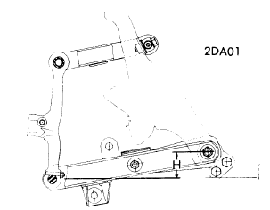
BMW
2002 Models - While rotating wheel hub, tighten castle nut to 22-24 ft. lbs., then rotate hub at least two more times. Loosen castle nut until bearing end play is noticed. Tighten castle nut to a maximum of 2.2 ft. lbs., then loosen nut to nearest hole and install cotter key. NOTE - After adjustment slotted washer should move easily, without noticeable resistance.3.0 Si and 530i Models - While rotating wheel hub, tighten castle nut to 7 ft. lbs. Loosen castle nut approximately 1/4 turn. Insert screwdriver in recess of bearing retainer washer and ensure washer can be rotated easily. Install suitable gauge holder (BMW 00 2 500) on wheel hub and install dial indicator with tip touching front axle stub. Move wheel hub back and forth several times and check bearing end play. Adjust castle nut until bearing end play is .0008-.0024". NOTE - Set bearing end play as close to lowest limit as possible. Install cotter key.
CAPRI
All Models - Rotate wheel, hub, and drum assembly while turning adjusting nut to 17-25 ft. lbs. Back off nut one-half turn. Retighten adjusting nut to 10-15 INCH lbs. Reinstall cotter pin and check front wheel rotations.
COURIER
All Models - While rotating wheel, hub and drum assembly, tighten adjusting nut to 17-25 ft. lbs. Back adjusting nut off 1/2 turn and retighten nut to 6-8 ft. lbs. Install new cotter key and check wheel rotation.DATSUN
All, Except F10 - Tighten spindle nut to torque specifications in table. Spin wheel and retorque spindle nut. Loosen nut according to specification in table and then tighten to align cotter key hole. Insert cotter key.F10 - Raise vehicle and place on safety stands. Remove tire and wheel. Make sure mounting nut is torqued to 87-145 ft. lbs. (12-20 mkg). Spin wheel hub several times in both directions to ensure free rotation. Measure bearing preload by attaching a spring pull scale to lug stud and turning hub. It should take about 3-11 lb. (1.4-4.9 kg) to turn hub.
FIAT
Model 124 and 131 - While rotating hub, torque spindle nut to 14.5 ft. lbs. Completely loosen nut and retighten to 5 ft. lbs. Loosen nut 30 degrees and stake collar of spindle nut into machined slot on spindle. Attach dial indicator with magnetic base on brake drum and actuating foot on spindle. Hub end play should not exceed .004" NOTE - When ever spindle nut has been removed it must be replaced with a new nut.Models 128 and X1/9 - Tighten front and rear spindle nuts to 112 ft. lbs. When spindle nuts are properly tightened, stake collar of spindle nut into machined slot on spindle.
1975 BMW Models Wheel Alignment Guide
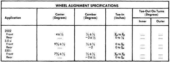
BMW SPECIFICATIONS AND ADJUSTMENTS
TIRE INFLATION (COLD)
Before attempting to check or adjust wheel alignment, ensure tires are properly inflated. The 2002 series requires 26 psi front and rear. The 3.0 series require 30 psi front and rear. The 530i series requires 28 psi front and 26 psi rear.
CASTER AND CAMBER
All Models - Before checking caster and camber, vehicle must be in loaded condition. Loaded condition consists of two 143 lbs. weights on front seat, one 143 lbs. weight on rear seat, gas tank full and 66 lbs. on left side of luggage compartment. If caster and camber are not within specifications check suspension for damage. Repair or replace parts as necessary.
TOE-IN
All Models - Before checking toe-in, vehicle must be in loaded condition (see Caster and Camber). Check toe-in with front wheels in straight-ahead position. If not within specifications, loosen tie rod clamping bolts. Rotate both tie rod tubes until toe-in is within specifications. Tighten clamping bolts.
Sunday, November 27, 2011
1976 Import Models Wheel Alignment Guide
BMW
TIRE INFLATION (COLD)
Before attempting to check or adjust wheel alignment, ensure tires are properly inflated. The 2002 series requires 26 psi front and rear. The 3.0 series requires 30 psi front and rear. The 530i series requires 28 psi front and 26 psi rear.
CASTER AND CAMBER
All Models - Before checking caster and camber, vehicle must be in loaded condition. Loaded condition consists of two 143 lbs. weights on front seat, one 143 lbs. weight on rear seat, gas tank full and 66 lbs. on left side of luggage compartment. If caster and camber are not within specifications check suspension for damage. Repair or replace parts as necessary.
TOE-IN
All Models - Before checking toe-in, vehicle must be in loaded condition (see Caster and Camber). Check toe-in with front wheels in straight-ahead position. If not within specifications, loosen tie rod clamping bolts. Rotate both tie rod tubes until toe-in is within specifications. Tighten clamping bolts.
CAPRI
ADJUSTMENT
TIRE INFLATION (COLD)
Before attempting to check or adjust wheel alignment, make sure that tires are properly inflated. Refer to manufacturer's specifications, located inside glove box door.
CASTER
All Models - Caster is nonadjustable. If not within specifications, check front suspension for damage. Repair or replace parts as necessary
CAMBER
All Models - Camber is nonadjustable. If not within specifications, check front suspension for damage. Repair or replace parts as necessary.
TOE-IN
All Models - Position wheels in straight-ahead position and loosen tie rod end lock nut and clips securing bellows. To adjust toe-in, rotate tie rods until specifications are within limits. Tighten lock nuts and secure clips. Tie rods lengths should be equal within 1/4".
COURIER
TIRE INFLATION
Before attempting caster or camber adjustment, ensure tires are correctly inflated. Specifications are located on glove box door; especially consider radial tires, they require a different pressure than conventional tires.
NOTE - Vehicle must be unloaded, except fuel, water and oil should be at their proper levels.
CASTER
To correct caster, adjust shims between upper control arm and frame or turn control arm shaft until correct angle is obtained (see specifications).
CAMBER
The camber is adjusted by adding or subtracting shims between the upper control arm and frame. Shims are available in the following sizes: .040", .064", .080", and .128". Set camber to specifications as shown in chart.
TOE-IN
1) Raise vehicle until front wheels clear ground. Turn wheel by hand and scribe a line in center of each tire thread. Measure distance between marked lines in front of front wheel and at rear of front wheel. Both measurements must be taken at equal distances from the ground.
2) If distance between wheels at rear is greater than that at front, but within specifications, adjustment is correct. If adjustment is wrong, loosen clamp bolts and adjust tie rod to specifications.
NOTE - Tighten clamping bolts with bolts horizontal and below steering link to prevent interference with center steering link.
DATSUN
ADJUSTMENT
TIRE INFLATION (COLD)
 |
| Fig. 1 Pickup Front Suspension Riding Height Measurement Points. |
Pickup Only - Make measurement with vehicle empty: Fuel tank full, radiator filled, oil levels up to marks, spare tire and hardware in position. Measure distance from center of lower control arm bushing (where it contacts to body) and lower steering knuckle bushing (See "H" in Fig. 1). To adjust, raise vehicle to release tension on acnhor bolt ajdusting nut and turn anchor bolt to adjust to specified height.
CASTER
All Models Exc. Pickup - Preset at factory and cannot be adjusted. If not to specifications, check suspension for wear or damage and repair or replace components as necessary.
Pickup - Caster is adjusted by increasing or decreasing thickness of shims inserted between upper link spindle and upper link mounting bracket. When front shim thickness increases, caster decreases. NOTE - Do not adjust caster with difference between front and rear shim thickness beyond .079" (2 mm).
CAMBER
All Models (Exc. Pickup) - Preset at factory and cannot be adjusted. If not to specifications, check suspension for wear or damage and repair or replace components as necessary.

Pickup - Camber is adjusted by increasing or decreasing the thickness of shims inserted between upper link spindle and upper link mounting bracket. When thickness of shim increase, camber decreases.
TOE-IN
All Models Except Pickup - Adjust by loosening each side steering link lock nut and adjusting steering link to change toe-in. NOTE - Left and right side steering links should be adjusted equally. Tighten lock nuts.
Pickup - Adjust by loosening steering cross link lock nuts, and adjust steering cross link to to change toe-in. Tighten lock nuts.
FIAT
ADJUSTMENT
TIRE INFLATION (COLD)
Before attempting to check or adjust wheel alignment, make sure tires are properly inflated. Refer to manufacturers specification given in owner's manual.
CASTER
Model 131 and 128 (Except. Sport L) - If caster is not to specifications, raise front of vehicle. Remove stabilizer bar-to-control arm nut and disconnect control arm from body. Remove end of stabilizer bar from control arm. To adjust caster, addition of shims between end of stabilizer bar and rubber pod of control arm will decrease caster angle and removal of shims will increase caster angle. Reverse removal procedure and recheck caster.
Model 128 Sport L - If caster is not to specifications, adjust by adding or removing shims located between stabilizer bar bushing and frame.
Model 124 - If caster is not within specifications, raise front of vehicle and remove wheel and shock absorber. Using suitable tool (A.74174), compress spring to relieve lower control arm and loosen nuts holding control arm pivot bar to crossmember. To adjust caster, remove shims from front stud and move to rear stud to increase caster. To decrease caster, remove shims from rear stud an move shims to front stud. Reverse removal procedure and check caster.
Model X1/9 - If caster is not to specifications, adjust by adding or removing shims located between stabilizer bar and stabilizer bar support.
CAMBER
Model 124 - If camber is not within specifications, adjust by changing shims. Raise front of vehicle, remove wheel and shock absorber. Using suitable tool (A.74174), compress spring to relieve lower control arm and loosen nuts holding control arm pivot bar to crossmember. To increase camber, remove equal amount of shims form both studs and add equal amount of shims to decrease camber. NOTE - Adding or removing equal amount of shims will not affect caster. Reverse removal procedure and check camber.
Model 128 and 131 Front - Camber is nonadjustable. If not within specifications, inspect suspension for damage and repair or replace parts as necessary.
Model 128 Rear - If rear camber is not within specifications raise rear of vehicle and compress one end of leaf spring, shifting it from flexible guide anchoring spring to control arm. Remove guide and slowly release spring. Remove nuts attaching pivot to body and loosen screw to free adjustment shims. To increase camber, add on equal number of shim on both screws attaching control arm to body. To decrease remove equal number of shims from both screws. Reverse removal procedure and check camber.
Subscribe to:
Posts (Atom)