Friday, February 17, 2012
Courier 1972-74 Drive Axle Repair Manual
Courier (1972 to 74) Repair Manual
DESCRIPTION
This axle assembly incorporates a removable carrier differential, having a hypoid type ring and pinion gear set, with the pinion being retained in the carrier by a companion flange and nut. Semi-floating axles are secured in the housing by the shaft bearing retainers.
IDENTIFICATION
Only one type of axle assembly is used. Axle ratio (4.11-1, 4.37-1 or 4.62-1) can be determined by dividing the number of teeth on ring gear by the number of teeth on pinion gear.
REMOVAL AND INSTALLATION
AXLE SHAFT AND BEARINGS
Removal - After removing complete brake assembly, including nuts securing backing plate and bearing housing-to-axle housing, slide axle shaft out of housing. Remove inner oil seal from axle shaft, spread locking tabs on lock washer, then using a suitable spanner (T72J-4252) remove lock nut and washer. Using a suitable puller (T72J-1225), remove bearing with housing from shaft. Remove bearing cap and outer seal from bearing housing.
Installation - Using suitable tool (T72J-1177), install new outer seal in bearing housing. Press or drive new bearing cup into retainer using suitable tool (T72J-4252-B). Install brake backing plate and bearing housing on axle shaft, then position bearing on axle shaft. NOTE - Insure bearing taper points in the right direction. Slide a suitable tool (T72J-4252-A) over shaft, place axle shaft on end in press, and press bearing into place. Install axle shaft and loosely assemble two bolts through bearing housing and axle housing. flange. Mount a dial indicator to backing plate so axle end play can be measured.
NOTE - If both axles have been removed, check end play of each shaft as it is installed. If end play is not to specification, adjustment is made by using appropriate shims between axle housing flange and bearing housing. After correct end play is obtained, install and tighten as necessary, all remaining components.
 |
| DIFFERENTIAL ASSEMBLY |
DIFFERENTIAL CARRIER
 |
| REAR AXLE ASSEMBLY |
Removal - Raise and support vehicle. Drain lubricant from differential, replace drain plug, then remove remove axle shafts as previously outlined. Mark drive shaft and companion flange at differential for reference at time reassembly, then remove drive shaft. Remove carrier-to-housing retaining nuts, then remove carrier from housing.
Installation - Reverse removal procedure using a suitable sealer between the carrier and axle housing, and insure the drive shaft-to-companion flange reference marks are aligned.
OVERHAUL
DISASSEMBLY
 |
| CHECKING RING GEAR BACKFACE RUNOUT (TYPICAL) |
1) Remove differential carrier as previously outlined, then mount carrier assembly in a suitable holding fixture with ring gear facing upward. Mount a dial indicator to carrier housing and check ring gear runout for reference at time of reassembly. Also make a gear tooth contact pattern check. Refer to Rear Axle Gear Tooth Patters in this section.
2) Punch mark differential bearing caps and adjusters for reference at time reassembly. Remove adjuster lock plates. Loosen bearing cap nuts and back off adjusters using a suitable spanner (T72J-4067). NOTE - Adjuster on left has left hand thread. Remove nuts, bearing caps, and adjuster, keeping each bearing cap with its own adjuster.

3) Lift out differential assembly keeping each bearing outer race with its own bearing. To remove differential bearings, use a suitable puller (T70P-4221). Remove bolts and locks retaining ring gear to case, then remove ring gear. Drive out differential pinion shaft lock pin and remove pinion shaft and thrust black. Rotate pinion gears 90 degrees and remove them with their thrust washers. Lift out the differential side gears along with their thrust washers.
4) Hold pinion gear companion flange and remove nut then the flange. Remove drive pinion and rear bearing. NOTE - If required, use soft headed mallet to top pinion gear from case, and guide pinion out to avoid damage to gear teeth. Remove oil seal and front bearing. Remove pinion bearing races from carrier using a drift in the slots provided. Remove and save the shims under the outer race, and remove bearing from pinion using a suitable tool (T72J-4630).
REASSEMBLY AND ADJUSTMENT
 |
| POSITIONING DRIVE PINION SHIMS AND BEARING CONES |
Case Assembly 1) If original ring and pinion gear set is being install, use original shim pack found under the pinion bearing outer race. If a new gear set is being used, determine the correct number of shims to use in the following manner: Drive pinion gears may be stamped either "+1,2,3" or "-1,2,3", or they may be unmarked. Compare marks on tapered ends of old and new gears. Subtract the two numbers. A plus remainder means to remove that number of shims from the original shim pack. A minus remainder means to add that number of shims to the original shim pack. If the number is the same on both gears, or if both gear are unmarked, use the original shim pack. Each shim is .0004" (.01 mm) thick, and no more than four shims should be used.
 |
| INSTALLING DRIVE PINION BEARING CONES |
2) Install the correct shim pack and then using a suitable tool (T72J-4616), install pinion gear bearing cases. Install bearing on pinion gear using a suitable tool (T70P-4625) and a press. Install pinion gear and bearing in carrier followed by the spacer, shims, front bearing and companion flange, without the oil seal. Tighten companion flange nut to 145-250 ft. lbs. (20.0-34.5 mkg).
3) Using an inch point torque wrench, check the rotating torque of pinion gear. If torque is not 15-30 INCH lbs. (17.3-34.6 ckg) through one complete revolution, refer to the shim thickness and spacer size tables and install appropriate shims and spacer which will obtain that specified preload. After setting preload, install the oil seal and reinstall the companion flange and nut.
Pinion Gear Shim Thickness
 |
| INSTALLING DRIVE PINION SPACER AND RING |
I.D. Mark Shim Thickness
4...................................................... .013" (.33 mm)
6...................................................... .014" (35 mm)
8...................................................... .016" (.38 mm)
Pinion Gear Spacer Size
I.D. Mark Length
20..................................................... 2.291" (58.19 mm)
28..................................................... 2.294" (58.27 mm)
36..................................................... 2.297" (58.37 mm)
44..................................................... 2.300" (58.42 mm)
Differential Assembly - Reverse disassembly procedure noting the following checks and adjustments.
Side-to-Pinion Gear Backlash - After installing side and pinion gears, insert pinion shaft, without thrust block, into its proper position. Check side-to-pinion gear backlash. If backlash exceeds .008" (.20 mm), refer to table and install appropriate side gear thrust washers to obtain the correct backlash. Remove pinion shaft, then reinstall it with the thrust block
Side Gear Thrust Washers
I.D. Mark Thickness
6................................................ .063" (1.6 mm)
7................................................ .067" (1.7 mm)
8................................................ .071" (1.8 mm)
 |
| CHECKING RING-TO-DRIVE PINION BACKLASH (TYPICAL) |
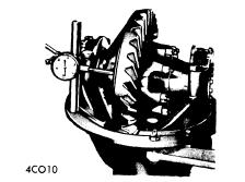
Ring-to-Drive Pinion Gear Backlash - After differential is completely assembled and installed in carrier, snug bearing cap nuts. Turn adjusters, using spanner, until bearings are properly seated and end play is eliminated with a slight amount of ring-to-drive pinion gear backlash. Slightly tighten one bearing cap nut on each side. Mount dial indicator to carrier flange with indicator plunger set at right angle to ring gear teeth. Check ring-to-drive pinion gear backlash at four or five points around ring gear. Turn both adjusters equally to obtain specified backlash. Proceed by setting differential bearing preload.

Differential Bearing Preload - Taking car not to disturb ring-to-drive pinion gear backlash, set preload using a dial indicator as shown in illustration. After setting preload, tighten bearing cap nuts and complete assembly procedure.


Colt 1971-74 Drive Axles Repair Manual
Colt 1971-74
DESCRIPTION
Rear axle is of the banjo type, utilizing the removable carrier style differential. Light weight construction joins split tublar housing for each side with center covers welded to alxe housing. Final drive is of the hypoid style. Axle shafts are semi-floating type supported with bearings at their respective ends in axle housing. Bearings are fitted to axles with pressure type bearing retainers. Pinion bearing preload, side bearing preload, and pinion depth adjustments are made with shims while differential side gears are adjusted with spacers.
AXLE RATIO AND IDENTIFICATIONS
Colt does not attach any tag or other easily identified item to the rear axle housing. Colt vehilce do however, utilize only one kind of rear axle assembly: Removable carrier. NOTE - In 1974 there were two different types of differential cases, side gears, and pinion gear.s When replacing these components, ensure proper parts are selected.
Differential Gear Radio
Application Axle Radio
1971-73........................................................... 3.889-1
1974
97.5" Engine............................................. 3.869-1
121.7" Engine........................................... 3.545-1
REMOVAL AND INSTALLATION
AXLE SHAFTS AND BEARINGS
Removal - 1) Raise and suitably support rear axle housing so rear wheels clear ground. Remove rear wheel and brake back plate nuts, then disconnect wheel cylinder brake line. Fix suitable puller set (CT-1003 & C-637) to lug studs and work slide hammer until axle shaft is free to be withdrawn. Set brake back plate with parking brake attached out-of-way. Using suitable tool (C-637 with hook) remove axle shaft oil seal.
2) To remove axle bearing proceed as follows. Grind down bearing retainer at one point until retainer thickness is .04-.06" (1.0-1.5 mm), then chisel ground portion and remove retainer. Using suitable bearing puller or press (CT-1120) remove bearing from axle.
3) Using a dial indicator, inspect axle shaft deflection in three spots (see illustration). Replace axle shaft if specifications are exceeded
Axle Shaft Deflection Table
Application Std. Value Service Limit
Point "A".................... 0-.004"............................ .004"
(0.-.10mm) (.10 mm)
Point "B"..................... 0-.002"............................. .002"
(0-.05 mm) (.05 mm)
Point "C"..................... 0-.08"................................ .08"
(0-2.0mm) (2.0 mm)
 |
| MEASURING AXLE SHAFT DEFLECTION |
5) Inspect wheel hub bolts for tightness and bearing outer retainer for deformation, replace defective parts as necessary.
Installation - 1) Fit outer bearing retainer flat side against shaft splined end, then install bearing and inner bearing retainer. Seat bearing retainer with smaller chamfered side directed to the bearing NOTE - Ensure bearing is completely seated.
2) Lightly coat lips of oil seal and using suitable oil seal installer (DT-1007B and CT-1008) fit axle shaft oil seal in rear axle housing.
3) Using packings and shims in proper sequence, set clearance between bearing and outer bearing retainer to .00-.01" (.0-.25 mm).
 |
| REAR AXLE SHAFT COMPONENTS |
DIFFERENTIAL CARRIER
Removal - Drain oil from rear axle differential housing, then disconnect propeller shaft. Pull out both rear axle shafts approximately 2 1/2". Remove differential gear housing mounting nuts and withdraw the differential gear carrier. It may be necessary to top outside of housing to break gear carrier loose.
 |
| REMOVING DIFFERENTIAL GEAR HOUSING |
OVERHAUL
Differential Gear Assembly - 1) Remove bearing carrier cap and lever gear case assembly from housing. Using suitable bearing puller tool (C-293-P and C-293-39) pull differential side bearing. Keep right and left bearings and shims in sequence for reassembly. |
| REMOVING DRIVE PINION BEARING |
Drive Pinion Disassembly - 1) Hold end yoke with suitable tool (C-3281) and remove lock nut, then remove end yoke. Using a wheel puller, force out drive pinion with adjusting shim, rear inner bearing race, spacer and preload adjusting shim.
 |
| REMOVING DIFFERENTIAL PINION SIDE BEARINGS |
INSPECTION
Check differential gears for correct tooth contact and replace gears of wear is excessive. Inspect bearing faces for roughness or score marks and replace, if necessary, bearing assembly. Ensure splines of side gears and rear axle shafts fit correctly. Check clearance between pinion gears and pinion shaft, if wear is excessive, replace components. |
| REMOVING FRONT DRIVE PINION OUTER RACE |
 |
| COLT SEPARATE HOUSING REAR AXLE ASSEMBLY |
REASSEMBLY AND ADJUSTMENT
 |
| CHECKING PINION & SIDE GEAR BACKLASH |
2) Check pinion and side gear backlash as shown in illustration. If backlash is beyond 0-.003" (0-.08 mm) adjust by selecting a side gear thrust washer (spacer) of correct size. If backlash is to be adjusted, ensure right and left sides are equally shimmed.
3) Thoroughly clean all dirt from ring gear mounting surface of differential case. Install bolts and lock washers. Tighten bolts alternately in a diagonal sequence and bend over lock tabs. Ensure lock washers are in contact with case rib after final torque has been performed.
Drive Pinion - Using a suitable drift and hammer or a press, seat front and rear bearing outer races into gear carrier ensuring that outer races do not cock. Ensure bearing races are completely seated before proceeding. Install shim between drive pinion and rear bearing. Using suitable bearing installer (CT-1075) press bearing onto drive pinion shaft. If drive pinion and bearing are scheduled to be reused, shims should be replaced with new ones of some thickness. In instances where the gear set is to be replaced, install new shims that are the same thickness as the used shims on drive pinion. NOTE - When determining the desired thickness of shim pack, amount of compression (sinkage) of shim pack and wear of the bearing (where old bearing is reused) must be taken into consideration.
Drive Pinion Depth - Install drive pinion spacer, front bearing, washer, end yoke and waher in order of removal. Fit pinion shaft retaining nut and slowly tighten nut, continuously checking, until pinion bearing preload is 6-9 INCH lbs. (7-10 cmkg) with oil seal not installed. Place suitable cylinder gauge on inside bearing pedestals of gear carrier housing. Place a black gauge on top end of drive pinion and slip a feeler gauge between the two gauges to obtain the correct clearance. The clearance between gauges should be .0118" (.300 mm). This is the standard height and any deviation from this height will be marked on the head of the pinion shaft and side of ring gear. To calculate the correct pinion height, add or subtract the variation value from the standard height. NOTE - Stamped values are in hudredth millimeters. Add or subtract the correct amount of shims as necessary.
Pinion Bearing Preload - This adjustment must be performed after the setting of the drive pinion depth. Remove end yoke and insert the bearing preload adjusting shim between pinion spacer and bearing, then tighten end yoke to 9-11 INCH lbs. (10-13 cmkg). In addition to the preload adjusting shims there are spacers available to provide proper adjustment. After finishing adjustment of drive pinion bearing preload remove the end yoke and apply a thin coat of grease to outer surface of oil seal, then drive seal into position in gear carrier. After greasing oil seal lip, insert end yoke and tighten nut.
Side Bearing Preload - Fit each side bearing into differential case leaving shims out; use suitable tool (CT-1102) for this procedure. Ensure side bearing are completely seated before proceeding. Install differential case assembly on gear carrier, then calculate the clearance between side bearing outer race and gear carrier as shown in illustration. After obtaining clearance add .002" (.05 mm) preload figure to each side, Insert shims equally on both sides. Align gear carrier and bearing cap index marks, then tighten cap retaining bolts.
 |
| MEASURING CLEARANCE BETWEEN SIDE BEARING AND GEAR CARRIER |

NOTE - Check gear tooth contact using point impression method described to beginning of this section.
Final Inspection and Assembly - Ligthtly coat each gear and bearing before and during reassembly with gear oil. After installing each component, ensure oil rotating parts are free to move smoothly. Install differential gear assembly to axle housing after applying sealing agent and tighten gear carrier mounting nuts in diagonal sequence.
Wednesday, February 15, 2012
Capri 1971-74 Drive Axles Repair Manual
ALL MODELS (1971-74)
DESCRIPTIONAn integral type housing, hypoid design, with centerline of pinion set below centerline of ring gear. Semi-floating axle shafts are retained in housing by ball bearings and a bearing retainer at axle housing outer ends. All-adjustments are pre-formed using selective fit shims and gaskets.
REMOVAL AND INSTALLATION
AXLE SHAFT AND BEARINGS
1) Remove brake drum retainers and remove brake drum. Remove bolts securing bearing retainer plate to axle housing. These bolts are accessible through holes in axle shaft flange. Pull axle shaft and bearing assembly out of axle housing.
2) Loosen inner retainer ring by nicking it deeply with a cold chisel in several places. It will then slide off easily. press bearing and seal assembly from axle shaft using arbor press and suitable tool to hold and support bearing.
3) To install, inspect housing and axle shaft and lightly coat wheel bearing bore with axle lubricant. Place bearing retainer plate on axle shaft, and press new wheel bearing on shaft using suitable tool. NOTE - Do not attempt to press on both bearing and inner retainer at the same time.
4) Using suitable bearing installation tool, press bearing inner retainer ring on shaft until retainer seats firmly against bearing. Insert axle shaft in housing and engage splines. Top shaft into position. Install bolts securing bearing retainer plate and install brake and drum retainers.
REAR AXLE ASSEMBLY
1) Raise vehicle and remove wheels. Mark propeller shaft for proper alignment and disconnect from drive pinion flange. Release parking brake; then rmeove locknut and adjusting nut from handbrake cable and disconnect cable from relay lever. Disconnect brake line from brake hose.
2) Raise and support center of rear axle and disconnect shock absorbers from axle. Remove rear axle support. Remove two stabilizer bar retaining clamps from rear axle housing. Remove rear spring "U" bolt nuts and detach bolts and plates. Lift axle assembly and remove from vehicle.
3) To install, lift rear axle assembly into position on spring, being sure that it is correctly located over spring pilot bolts. Align and loosely fit propeller shaft to drive pinion flange. Fit "U" bolts over axle, slide on lower plates, install new locknuts and tighten.
4) Using a suitable tool, hold rear stabilizer bar onto mounting pads on axle housing and install retaining clamps. Insert retaining clamp bolts, check for binding, and tighten. Raise center of rear axle and install shock absorbers. Remove axle support.
4) Using a suitable tool, hold rear stabilizer bar onto mounting pads on axle housing and install retaining clamps. Insert retaining clamp bolts, check for binding, and tighten. Raise center of rear axle and install shock absorbers. Remove axle support.
5) Reconnect brake line to brake hose and handbrake cable to relay lever on rear axle housing. Adjust nut until relay lever is just clear of stop, tighten locknut. Tighten driveshaft to pinion flange bolts and bleed rear brake system. Fill rear axle housing with lubricant, mount rear wheels and lower vehicle.
OVERHAUL
DIFFERENTIAL CASE
Disassembly - 1) Raise vehicle and remove wheels and axle shaft assemblies. Mark propeller shaft for correct realignment and disconnect from pinion flange. Remove ten cover attaching bolts, cover and gasket and drain rear axle oil. Discard gasket and thoroughly clean cover.
2) Remove differential bearing caps and mark caps for correct repositioning. Lift differential out of axle housing using two pry bars. Remove tapered roller bearing from each side of differential assembly using a suitable puller. Remove adjusting shims from differential housing. Remove ring gear attaching bolts and ring gear from differential assembly.
3) Using a suitable drift, remove locking pin securing differential pinion shaft in differential case and remove differential pinions, side gears and adjusting shims. Hold drive pinion flange and remove pinion nut, retain nut for use during assembly operations. Remove pinion flange using a suitable puller, then remove pinion from axle housing. Remove bearing spacer from pinion. Remove large roller bearing from pinion shaft using press and suitable fixtures. Remove small tapered shaft using press and suitable fixtures. Remove small tapered roller bearing and seal from axle housing using a suitable drive. Drive bearing races out from axle housing with a drift.
 |
| CHECKING PINION DEPTH |
2) Install dummy pinion (part of special tool) into axle housing with pinion bearing but no shims. Lightly lubricate bearings and tighten tool until correct pinion bearing pre-load is obtained. Rotate dummy pinion several times to unsure seating of bearings. It is essential that the torque reading be recorded and followed for further adjustment of drive pinion. This torque must also be check after installation of drive pinion with selected spacer.
3) Mount dial indicator on mounting bracket and set to zero on dummy pinion. Slowly rotate dial indicator over cross bar of tool and read total deflection of pointer. This reading gives the exact thickness of the shims to be used. When pinion is marked "-1" or "-2" this amount must be added to indicator reading. When gear is marked "+1" or "+2" this amount must be subtracted from reading to obtain correct shim thickness. Using a micrometer, select a shim of the determined thickness.
 |
| MEASURING SIDE GEAR CLEARANCE |
5) Position ring gear on differential case and locate with bolts. Pull ring gear evenly into position with bolts. Remove old bolts and install new bolts and tighten. To determine total play of differential case in axle housing: Press tapered roller bearing onto differential case without shims after first inspecting bearings for damage. Install pressure blocks (part of tool 170P-4136) into axle housing on each side of differential case and install bearing caps (number to number) and tighten attaching bolts. Now, loosen and tighten finger tight.
6) Tighten pressure spindle (tool T70P-4136) to a torque of 43 INCH lbs. Rotate differential several times and recheck torque. Mount dial indicator on rear axle housing so that feeler attach inner side of ring gear flange and zero indicator. Place pressure spindle into other side of housing and tighten to 43 INCH lbs. Read and note amount of indicator delfection and record as total play of differential case is rear axle housing. Loosen pressure spindle, tilt dial indicator to side and remove differential, pressure spindle and pressure blocks.
7) To determine thickness of pinion bearing spacer: Slide master spacer (tool T70P-4137) onto pinion. Using soft wire solder of about .08" (2 mm) diameter, form a ring which matches drive pinion shaft diameter and place it onto gauge ring. Position pinion into rear axle housing and slid on small taper roller bearing and pinion flange. Install old self-locking nut, hold drive pinion flange and slowly tighten nut to its specifications using care not to exceed torque value or procedure must be respected with new solder wire. Carefully remove compressed solder wire and measure thickness at two opposite points. If thickness varies, average the two values.
 |
| DIFFERENTIAL SETUP & BLOCKS INSTALLATION |
9) To determine differntial case bearing shim thickness. Place pressure blocks back into axle housing and place differential case with bearing races into axle housing. Install bearing caps, tighten screw, then loosen and tighten finger tight. Using pressure spindle, press differential housing with a torque of 43 INCH lbs. away from drive pinion. Rotate pinion several times. Position feeler of dial indicator gauge at right angle to one tooth of ring gear. Measure tooth flank backlash at 4 points, each time turning gear two bolt heads further. Deviations of tooth flank backlash must not exceed .002" (.05 mm). Insert pressure spindle into other side of axle housing and screw in slowly until there is the specified value of tooth flank backlahs.
10) Position dial indicator so that feeler contact ring gear flange and zero indicator. Insert spindle into the other side of axle housing and torque to 43 INCH lbs. Read and record indicated deflection on indicator as ring gear back side shim thickness. Remove pressure spindle, differential case and pressure blocks from axle housing.
 |
| MEASURING RING GEAR BACKLASH |
12) Remove differentail case bearings and position required shims on differential case. Using suitable tools, press tapered roller bearing onto differential case after checking bearing for damage. Insert differential case in axle housing and position bearing caps as previously marked. Coat bolt threads with sealing compound and insert bolts.
13) Position dial indicator feeler in a vertical position on one ring gear tooth and check that pinion to ring gear backlash is to specifications. If not, differential must be removed and shims adjusted. If backlash is too greast, remove shims from ring gear face side and transfer to ring gear back side and vise versa. Do NOT increase or decrease number of shims, but only interchange between one side and the other.
14) Finally check gear contact pattern and adjust as necessary to obtain correct patter. Position housing cover and gasket on axle housing and install and tighten bolts. Attach parking brake operating lever to rear axle housing and connect return spring to bracket on housing. Install rear brake assemblies on axle housing and connect parking brake cable to brake assemblies.

Monday, February 13, 2012
Austin Healey Sprite & MG Midget Drive Axles Repair Guide
Austin Healey Sprite (1968-70)
MG Midget (1968-74)
DESCRIPTION
Rear axles are hypoid design with center line of pinion set below centerline of ring gear. The axle shafts, pinion and differential assembles can be serviced without removing axle from vehicle. All differential adjustments are performed using shims. No adjustment for axle shaft end play is necessary.
AXLE RATION AND IDENTIFICATIONS
Only one basic axle design is used on these models. To determine axle ratio, divide number of ring gear teeth by number of pinion gear teeth.
REMOVAL AND INSTALLATION
Axle Shaft and Bearings
1) With rear of vehicle raised and wheels removed, release handbrake and back off brake shoe adjuster. On models with disc wheels, remove brake drum locating screws and top drums off hubs. Remove axle shaft retaining screw and withdraw shaft from hub assembly. On models with wire wheels, remove nuts securing drum to hub and tap brake drums off hub. Remove retaining screws securing hub extension flanges to hubs. Withdraw hub extensions and axle shafts.
2) Using suitable tool, remove hub nut and lock washer. Withdraw hub complete with bearing and seal. To install, repack hub bearings with grease and press hub into position. If paper washer or "O" ring was damage on disassembly, they must be replaced. If seal was removed, drift it into position using suitable tool. Drift hub, into axle housing using suitable tools and reinstall remainder of components in reverse of disassembly procedure.
PINION FLANGE AND SEAL
1) Mark propeller shaft and pinion flange for proper realignment and disconnect propeller shaft. Unscrew nut in center of flange, using suitable tool to prevent flange from rotating. Remove nut and washer and withdraw flange and pressed end cover from pinion shaft. Extract oil seal from axle housing.
2) Press new seal into axle housing with edge of sealing ring facing inwards. Replace flange and end cover, taking care not to damage edge of oil seal. Tighten pinion flange nut and reconnect propeller shaft, ensuring that index marks are fixed up.
DIFFERENTIAL CARRIER
Drain rear axle and remove axle shafts. Mark propeller shaft and pinion shaft for correct reassembly and disconnect shaft. Remove nuts securing differential carrier to axle housing and withdraw complete carrier. To install, reverse removal procedure.
OVERHAUL
Dissassembly
1) Check to ensure that differential bearing caps are marked to ensure correct replacement, then remove bearing cap nuts, washers and caps. Remove differential cage. Remove differential bearings from cage, using suitable tools and not that the thrust face of each bearing is marked "THRUST" and that shims are installed between inner ring of each bearing and differential cage. Knock back tabs of locking washers and unscrew bolts securing ring gear to differential cage, remove ring gear.
2) Tap out pin locating differential pinion shaft from ring gear side of cage as tapered pins are used. Drive out differential pinion shaft and remove pinions and thrust washers from cage. Remove pinion nut, flange and pressed end cover. Drive pinion shaft towards rear through carrier. Pinion shaft will come out with inner race and rollers for rear bearing, leaving outer race and complete front bearing in position.
3) Tap out inner race of front bearing and oil seal. Withdraw outer races using suitable tools. Slide off pinion sleeve and shims. Withdraw rear bearing inner race from pinion shaft using suitable tools. Note spacing washer against pinion head. Remove rear bearing outer race using suitable tools.
INSPECTION
Clean and inspect all components for worn or damaged parts. The ring and pinion gear must be replaced as a matched set if replacement of either is necessary.
REASSEMBLY AND ADJUSTMENT
 |
| CALIBRATING DIAL INDICATOR (TOOL 18G-191 |
2) Install inner ring of front bearing and pinion flange and tighten nut slowly until a bearing preload of 8-10 inch lbs. (9-12 kgcm) is obtained. Using tool 18G-191, adjust dial indicator to zero on machined step "A" of setting block (see illustration). Place dial indicator and base of tool on head of pinion and position tool so dial indicator feeler rest from zero. Now swing indicator to other bearing bore and again note variation from zero. Average the two variations together.
3) Take into consideration any variation in pinion head thickness. This will be shown as an unbracketed figure etched on pinion head and will always be minus. If no unbracketed figure is shown, pinion is of nominal thickness. Using the average dial indicator reading just obtained and the unbracketed figure from pinion head, perform the following calculation. If indicator reading is minus, add indicator reading to pinion head reading and REDUCE known washer thickness by this amount
EXAMPLE:
 |
| CHECKING BEARING THICKNESS VARIATION (TOOL 18G |
Pinion Marking............................... -.005"
Variation from Nominal.................. -.007"
Reduce known washer thickness by this amount.
4) If indicator reading is plus and numerically LESS than pinion marking. REDUCE the known washer thickness by the difference.
EXAMPLE
Pinion Marking............................. -.005"
Indicator Reading......................... +.003"
Variation From Nominal............... -.002"
Reduce known washer thickness by this amount.
5) If indicator reading is plus and numerically GREATER than pinion marking, INCREASE the known washer thickness by the difference.
EXAMPLE:
Indicator Reading........................ +.008"
Pinion Marking............................ -.003"
Variation from Nominal............... +.005"
 |
| CHECKING BACKLASH (TOOL 18G-191) |
6) The only cases where no changes are required to washer thickness are when indicator reading is PLUS and NUMERICALLY EQUAL to unbracketed pinion marking, or indicator reading is zero and there is no unbracketed marking on pinion head. Allowance should now be made as follows for mounting distance marked on pinion head in a rectangular bracket as follows.
7) If marking is a PLUS figure, REDUCE washer thickness by on equal amount. If marking is a MINUS figure, INCREASE washer thickness by an equal amount. A tolerance of .001" (.03 mm) is allowed of washer finally installed.
Pinion Bearing Period - Install washer of thickness just calculated under pinion head and assemble pinion with bearings, pinion sleeve, oil seal, flange and nut. Pinion sleeve is of collapsible design and can only be used once. Therefore the following procedure should be done with care or a new sleeve will be required. Slowly tighten flange nut to specifications while holding flange to prevent rotation. During tightening process, occasionally check pinion bearing preload. When nut is tightened to specifications, preload should be to specifications. Installation of pinion is now complete.
Side Bearing Preload - 1) The method of setting position of ring gear assembly depends on marking given on differential gear carrier and case. The dimensions to be considered are (see illustration): "A" - The dimension from center line to bearing on right side. Variation in dimension "A" is stamped on carrier adjacent to right side bearing bore. "B" - The dimension from center line to bearing on left side. Variation is stamped on left side bearing bore. "C" - Dimension from bearing on one side of cage of bearing on the other side and "D" - Dimension from rear face of ring gear to bearing on opposite side. Variations are "C" & "D" dimension are stamped on machined face of differential cage.
 |
| SIDE BEARING PRELOAD DIMENSIONS |
A+D-C+.022"
Substituting the actual variation shown, this formula gives shim thickness required to compensate for variations in machining plus the extra .002" (.05 mm) to give necessary bearing preload. In addition, allowance must be made for variations in bearing thickness in the following manner:
3) Rest bearing with inner race over recess and thrust face downwards on surface plate of tool 18G-191. Place dial indicator on surface plate and zero indicator on step "A" of gauge block of tool 18G-191. Swing indicator over until it rests on plain surface of inner bearing race. Hold inner race down against balls and note indicator reading. Indicator will normally indicate a negative reading. This negative variation should be ADDED to the shim pack previously calculated for that side of the differential.
4) To calculate the shim thickness for the right side, use the following formula:
B-D+.006".
substituting the actual values for "B" and "D" as described in 1). Again, final allowance must be made for variation in bearing thickness describe in 3) above.
5) When a framed number is marked on back of ring gear, e.g. +2, it must be taken into account before assembling shims and bearings to differential cage. If, for example, the mark is +2, then shims of .002" must be transferred from left (ring gear) side to right side. If marking is -2, shims of .002" must be moved from right to left side.
Backlash Adjustment - 1) Assemble bearing (thrust faces outwards) and shims as calculated to differential cage. Bolt ring gear to differential cage but do not knock over locking tabs. Mount assembly on two "V" blocks and check runout by means of dial indicator. If runout exceeds specifications, remove ring gear and check joint faces on cage ring gear for any particles of dirt. If parts are thoroughly cleaned it is unlikely that ring gear will not run true. Tighten bolts and knock over locking washers.

Honda Accord 2008-09 Repair Manual
Manufacturer: Honda
Model: Accord
Year: 2008 to 2009
CONTAINS THE FOLLOWING INFORMATION AND REPAIRS FOR:

Model: Accord
Year: 2008 to 2009
CONTAINS THE FOLLOWING INFORMATION AND REPAIRS FOR:
- General Information
- Specifications
- Maintenance
- Engine Electrical
- Engine Mechanical
- Engine Assembly
- Cylinder Heads
- Engine Block
- Engine Lubrication
- Intake Manifold and Exhaust System
- Engine Cooling
- Fuel and Emissions
- Transaxle
- Clutch
- Manual Transmission
- Automatic Transmission
- Driveline/Axle
- Steering
- Suspension
- Brakes
- Body
- HVAC
- Body Electrical
- Audio, Navigation and Telematics
- Restraints
File Size: 89 MB
File Type: PDF, ZIP
Austin Marina 1973-73 Drive Axles Repair Guide
1973-74 Austin Marina
DESCRIPTION
Rear axles are hypoid design with center line of pinion set below centerline of ring gear. The axle shafts, pinion and differenctial assemblies can be serviced without removing axle from vehicle. All differential adjustments are performed using shims. No adjustments for axle shaft end play is necessary.
AXLE RATIO AND IDENTIFICATION
Only one basic axle design is used on these models. To determine axle ratio, divide number of ring gear teeth by number of pinion gear teeth.REMOVAL AND INSTALLATION
AXLE SHAFTS AND BEARINGS1) With rear of vehicle raised and wheel removed, remove axle shaft nut and washer. Remove screws retaining brake drum and remove drum. Withdraw rear hub from axle shaft using suitable tool. Disconnect handbrake cable and brake pipe. Remove nuts, washers and bolts retaining brake backplate to axle housing.
2) Note installed position of drip lip in relation to brake slave cylinder and remove oil catcher and backplate assembly. Remove rear hub oil seal and housing assembly. Remove oil seal from housing using suitable tool. Remove axle shaft key and place container under axle to collect oil spillage. Withdraw axle shaft from housing, using suitable puller. Remove inner oil seal and press bearing from axle shaft.
3) Pack bearing with lithium based grease and dip new oil seal in light oil before reassembling. Install new oil seal with lip of seal facing inwards. Press bearing onto axle shaft until dimension from bearing to threaded end of axle shaft is to specifications. Continue assembling in reverse of disassembly using a new rear hub joint washer and using "Lactite LT 270" or equivalent on axle shaft nut.
PINION FLANGE AND SEAL
1) Raise and support rear of vehicle. Mark propeller shaft and pinion flanges for correct realignment. Disconnect propeller shaft and remove flange nut split pin. Retain flange using suitable tool and remove nut and washer.
2) Place container under flange to collect oil spillage and remove flange and oil seal. To install reverse removal procedure noting the following: Soak new seal in light oil for one hour before installing. Install seal with lip of seal facing inwards.
DIFFERENTIAL CARRIER
Remove both axle shafts and mark differential pinion and propeller shaft for proper realignment on assembly. Disconnect propeller shaft. Place container under axle assembly to collect oil and remove nuts and washers retaining carrier to axle housing. Remove carrier. To reinstall, reverse removal procedure, using a new gasket and suitable gasket sealer.
OVERHAUL
Disassembly1) With carrier removed, mount unit upright in a vise and mark bearing caps for correct reassembly. Remove bearing cap bolts, washer and caps. Assemble suitable axle stretcher (18G-131) on unit casing and stretch unit case by tightening turnbuckle three or four flats until differential carrier can be levered out and bearing shims and caps removed. CAUTION - To avoid damaging case, do not spread any more than necessary. Maximum stretch is .008" (.20 mm). Do not pry against stretcher.
2) Remove gear carrier bearing caps and mark ring gear and carrier to ensure correct replacement. Remove ring gear retaining bolts and ring gear. Drive out pinion shaft locking pin, then drive out pinion shaft. Remove pinion gears and thrust washers. Remove differential gears and thrust washers. Remove drive flange nut cotter pin and drive flange nut. Using suitable puller, remove drive flange.
3) Press out drive pinion and remove pinion bearing shims and spacer. Using suitable press tools, remove inner bearing from pinion. Remove pinion head washer and drift out pinion outer bearing cup, bearing and oil seal. Drift out pinion inner bearing cup.
INSPECTION
Clean and inspect all components for wear or damage. Ring and pinion gears, differential bearings and pinion bearings must be replaced as matched sets.
REASSEMBLY AND ADJUSTMENT

Side Bearing Preload - 1) Install differential bearing comes in gear carrier using suitable tool. Install two differential gear carrier using suitable tool. Install two differential gears in carrier, ensuring each thrust washer is correctly positioned. Position two pinion gears, one each side of carrier and mesh them with differential gears. Using on axle shaft inserted in a differential gear, turn gears and ensure two pinions rotate into mesh and align with pinion shaft hole in carrier. Install pinion shaft.
2) Press each pinion firmly into mesh with differential gears and, asses required pinion thrust washer thickness required to achieve ZERO backlash. Remove pinon shaft and pinions and install thrust washers. Reinstall pinion gears and shfts with thrust washers and check that zero backlash exists. Lubricate components and install pinion shaft locking pin and secure by peening metal of differential carrier.
3) Clean ring gear mounting and carrier face and install ring gear, tighten bolts. Assembly carrier bearing cups to bearings and position assembly in case; do not install bearing shims. Install bearing caps in correct position. Using dial indicator and suitable adapters, ensure that ring gear runout does not exceed specifications. Remove bearing caps and press differential bearing cups onto bearings and move carrier assembly to one side of case. Zero dial indicator and move carrier assembly fully in opposit direction. The indicator reading should be noted for future references as "Total Side Floor". Remove differential assembly from case.

Drive Pinion Depth - 1) Install inner and outer pinion bearing cups to case using suitable tools. Install pinion inner bearing to dummy pinion (18G-191 M). NOTE - Dummy pinion incorporate standard pinion head washer of .077" (1.95 mm) thickness. Oil bearing and install dummy pinion, outer bearing, tool spacer, washer and nut. Tighten nut gradually until bearing preload specification is obtained. Clean dummy pinion head and position dial indicator gauge foot of tool 18G-191 on dummy head and zero indicator.
2) Move dial indicator over center of one differential bearing bore and note reading. Repeat for opposite bearing bore.
Average these two measurements and perform the following calculation.
EXAMPLE
Average of bore measurements.................. .0002" (.051 mm)
PLUS dummy pinion washer allowance..... .077" (1.956 mm)
Required size of pinion head washer ........ .079 (2.007 mm)
If the etched marking on pinon face is "N" (normal), no change to above dimension is required. If etched marking is positive (+), reduce size of required pinion washer by amount marked. If etched marking is negative (-), increase size required pinion washer by amount marked. Remove dummy pinion and remove inner bearing from dummy pinion.
Pinion Bearing Preload - 1) Place selected pinion head washer on pinion and install inner bearing using suitable tools. Oil bearing and install pinion in case. Install bearing spacer, chamfered end towards drive vlange. Install shims, oil and install outer bearing. Install drive flange washer and nut. Gradually tighten nut, but do not exceed torque specifications, and check preload during tightening operation.
2) Rotate flange to settle bearing and check preload with flange nut tightened to specifications. If preload is high, increase shim thickness. If preload is low, decrease shim thickness. NOTE - .001" shim thickness equals approximately 4 INCH lbs. (4.6 cmkg) preload. Remove drive flange nut and flange. Soak new oil seal in oil for one hour and then install seal. Install drive flange, washer and nut and tighten flange nut. Install new cotter pin.CHECKING BACKLASH

Adjusting Backlash - 1) Place bearing cups on differential bearing and install carrier in case. Position dial indicator with suitable adapters on ring gear side of case. Move ring gear fully into mesh with pinion and zero indicator on rear of ring gear. Move ring gear and carrier in opposite direction until bearing ring gear side is butted in housing. The indicated measurement should be noted as the "In-out" mesh clearance.
2) Perform the following calculation:
EXAMPLE
"In-Out" mesh clearance 1.......................... .025" (.63 mm)
MINUS Specified backlash......................... .005" (.13 mm)
Required ring gear side shim pack............. .020" (.50 mm)
"Total Side Floot" 2.................................... .060" (1.52 mm)
MINUS ring gear side shim pack............... .020" (.50 mm)

Required shim pack opposite ring gear ... .040" (1.02 mm)
1 - Value from 2) above
2 - Value from 2) under "Side Bearing Preload".
Add a value of .002" (.51 mm) to each shim pack calculated above for preload.
3) Stretch case specified amount and from calculations made above, select required shim pack. Install differential assembly in case with shim packs. Loosen case stretcher and remove. Install bearing caps as originally marked and tighten bolts. Rotate pinion to settle differential bearings and position dial indicator using suitable adapters to measure ring gear backlash. Measure backlash at several locations, it must be to specifications. If not, interchange shims from side to side to achieve specified backlash. NOTE - A movement of .002" (.05 mm) shim thickness from one bearing to the other will vary backlash by about .002" (.05 mm). Reinstall differential assembly in rear axle housing.

Monday, February 6, 2012
Volvo 1975 Models Wheel Alignment Guide
VOLVO SPECIFICATIONS AND ADJUSTMENTS
TIRE INFLATION (COLD)
Before attempting to check or adjust wheel alignment, make sure tires are properly inflated. Refer to manufacturers specifications given in owner's manual.CASTER
164 Series - If caster not within specifications, loosen bolts at upper control arm shaft using suitable tool (SVO 2713). Increase caster angle by adding shims at rear bolt or by removing shims from front bolt. To decrease caster angle, remove shims at front bolt or add shims to rear bolt. Tighten bolts and recheck caster angle.240 Series - If caster is not within specifications, loose nuts at strut assembly upper attachment. Use a special tool (9995038) at strut upper attachment to adjust caster to specifications, then tighten nuts and recheck caster.
CAMBER
164 Series - If camber not within specifications, loosen bolts at upper control arm shaft using suitable tool (SVO 2713). To increase camber angle, remove equal amount of shims from front and rear bolts. To decrease camber angle, add shims to front and rear bolts in equal amounts. Tighten bolts and recheck camber angle.240 Series - See 240 Series procedure under Caster adjustment.
TOE-IN
All Models - Place wheels in straight-ahead position and loosen lock nuts on steering links (tie rods). To adjust toe-in rotate adjustable sleeves until correct toe-in is obtained. Tighten lock nuts and recheck toe-in.
Subscribe to:
Posts (Atom)