Friday, March 23, 2012
Arrow/Colt 1976-77 Drive Axles Repair Manual
DESCRIPTION
Rear axle is of the banjo type, utilizing the removable carrier style differential. Light weight construction joins split tubular housings for each side with center covers welded to axle housing. Final drive is of the hypoid style. Axle shafts are semi-floating type supported with bearings at their respective ends in axle housing. Bearings are fitted to axles with pressure type bearing retainers. Pinion bearing preload side bearing preload, and pinion depth adjustment are made with shims while differential side gears are adjusted with spacers
REMOVAL AND INSTALLATION
Axle Shafts and Bearings
 |
| FIG. 1 MEASURING AXLE SHAFT DEFLECTION |
2) To remove axle bearing proceed as follows: Grind down bearing retainer at one point until retainer thickness is .04-.06" (1.0-1.5 mm), then chisel ground portion and remove retainer. Using suitable bearing puller or press (CT-1120) remove bearing from axle.
3) Using a dial indicator, inspect axle shaft deflection in three spots (see illustration). Replace axle shaft if specifications are exceeded.
4) Rear axle bearing should be replaced when bearing noise is detected, when bearing axial free play exceeds .014-.016" (.36-.41 mm) or if bearing radial free play exceeds .001-.002" (.03-.04 mm) at approximately 11 lbs. (5.0 kg) measuring force.
5) Inspect wheel hub bolts for tightness and bearing outer retainer for deformation ,replace defective parts as nessary.
Installation - 1) Fit outer bearing retainer flat side against shaft splined end, then install bearing and inner bearing retainer. Seat bearing retainer with smaller chamfered side directed to the bearing. NOTE -Ensure bearing is completely seated.
2) Lightly coat lips of oil seal and using suitable oil seal installer (DT-1007B & CT-1008) fit axle shaft oil seal in rear axle housing.
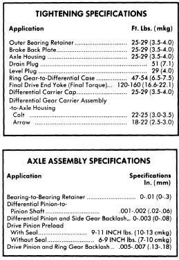
3) Using packings and shims in proper sequence, set clearance between bearing and outer bearing retainer to .00-.01" (.0-.25 mm).
4) Carefully insert axle shaft assembly into axle housing using care not to damage seal. Slightly turn shaft until splines line up with differential side gears. Align packing oil holes with outer bearing retainer and tighten bearing retainer to axle housing flange. Connect brake line to wheel cylinder and bleed air from system.
DIFFERENTIAL CARRIER
Removal - Drain oil from rear axle differential housing, then disconnect propeller shaft. Pull out both rear axle shafts approximately 2 1/3". Remove differential gear housing mounting nuts and withdraw the differential gear carrier. It may be necessary to top outside of housing to break gear carrier loose.
Installation - Lightly coat each bearing and gear with oil. Apply sealing compound on packing and axle housing seat, then assemble gear carrier to housing with nuts and tighten. Fill differential gear housing with .96 quart of suitable multi-purpose gear oil (API GL-5).
Differential Gear Assembly - 1) Remove bearing carrier cap and lever gear case assembly from housing. Using suitable bearing puller tool (C-293-P & C293-39) pull differential side bearing. Keep right and left bearings and shims in sequence for reassembly
2) Remove ring gear lock plate tabs and loosen bolts in diagonal sequence, then remove ring gear. Drive out pinion shaft lock pin from ring gear back side using a punch, pull out pinion shaft and pinion. Pinion side gears and spacers are now accessible. Note placement of side gear and spacers and ensure they are reassembled in same position.
Drive Pinion Disassembly - 1) Hold end yoke with suitable tool (C-3281) and remove lock nut, then remove end yoke. Using a wheel puller, force out drive pinion with adjusting shim, rear inner bearing race, spacer and preload adjusting shim.
2) With suitable bearing puller (C-293-P & C-293-39) remove rear bearing inner race and at same time, pull of dive pinion adjusting shim. Using suitable drift, remove front drive pinion bearing outer race and oil seal. Repeat some procedure to remove bearing outer race.
INSPECTION
Check differential gears for correct tooth contact and replace gears if wear is excessive. Inspect bearing faces for roughness or score marks and replace, if necessary, bearing assembly. Ensure splines of side gears and rear axle shafts fit correctly. Check clearance between pinion gears and pinion shaft, if wear is excessive, replace components.
NOTE - To check gear tooth contact using pain impression method, refer to beginning of this section.
REASSEMBLY AND AJDUSTMENT
Case Assembly - 1) Install thrust washers (spacers) behind side gears in their original position and assemble pinion and side gears in differential. Insert both pinion gears with pinion washers attached, so they mesh with side gears. It may be necessary to slightly rotate pinions to achieve desired meshing. Insert drive pinion shaft.
2) Check pinion and side gear backlash as shown in illustration. If backlash is beyond 0-.003" (0-.08mm) adjust by selecting a side gear thrust washer (spacer) of correct size. If backlash is to be adjusted, ensure right and left sides are equally shimmed.
3) Thoroughly clean all dirt from ring gear mounting surface of differential case. Install bolts and lock washers. Tighten bolts alternately in a diagonal sequence and bend over lock tabs. Ensure lock washers are in contact with case rib after final torque is performed.
Drive Pinion - Using a suitable drift and hammer or a press, seat front and rear bearing outer races into gear carrier ensuring that outer races do not cock. Ensure bearing races are completely seated before proceeding. Install shim between drive pinion and rear bearing. Using suitable bearing installer (CT-1075) press bearing onto drive pinion shaft. If drive pinion and bearings are scheduled to be reused, shims should be replaced with new ones of same thickness. In instances where the gear set is to be replaced, install new shims that are the same thickness as the used shims on drive pinion NOTE - When determining the desired thickness of shim pack, amount of compression the desired thickness of shim pack, amount of compression (sinkage) of shim pack and wear of the beating (where old bearing is reused) must be taken into consideration.
Drive Pinion Depth - Install drive pinion spacer, front bearing, washer, end yoke and washer in order of removal. Fit pinion shaft retaining nut and slowly tighten nut, continously checking, until pinion bearing preload is 6-9 INCH lbs (7-10 cmkg) with oil seal not installed. Place suitable cylinder gauge on inside bearing pedestals of gear carrier housing. Place a block gauge on top end of drive pinion and slip a feeler gauge between the two gauges should be .0118" (.300 mm). This is the standard height and any deviation from this height will be marked on the head of the pinion shaft and side of ring gear. To calculate the correct pinion height, add or subtract the variation value from the standard height.
NOTE - Stamped values are in hundredth millimeters. Add or subtract the correct amount of shims an necessary.
Pinion Bearing Preload - The adjustment must be performed after the setting of the drive pinion depth. Remove end yoke and insert the bearing preload adjusting shim between pinion spacer and bearing, then tighten end yoke to 9-11 INCH lbs. (10-13 cmkg). In addition to the preload adjusting shims there are spacers available to provide proper adjustment. After finishing adjustment of drive pinion bearing preload remove the end yoke and apply a thin coat of grease to outer surface of oil seal, then drive seal into position in gear carrier. After greasing oil seal lip, insert end yoke and tighten nut.
Side Bearing Preload - Fit each side into differential case leaving shims out; use suitable tool (CT-1102) for this procedure. Ensure side bearings are completely seated before proceeding. Install differential case assembly on gear carrier, then calculate the clearance between side bearing outer race and gear carrier as shown in illustration. After obtaining clearance add .002" (.05 mm) preload figure to each side. Insert shims equally on both sides. Align gear carrier end bearing cap index marks, then tighten cap retaining bolts.
Ring Gear Deflection - Attach a dial indicator to back side of ring gear and measure deflection. If ring gear has excessive deflection, correct position of the assembly in relation to differential case and again perform measurement. Replace ring gear or differential case as necessary.
Drive Pinion Depth - Measure backlash of drive pinion is at least four different spots on ring gear with drive pinion securely fixed in final position. Set up a dial indicator on ring gear teeth edges. If measured backlash is greater than .005-.007" (.13-.18 mm), shift shims from ring gear side to the back of the ring gear to obtain pro[er backlash. If the measure value is less than standard value, reverse the moving of shims as stated above. Side bearing shims are available in various thicknesses.
NOTE - Check gear tooth contact patter using point impression method described at beginning of this section.
Final Inspection and Assembly - Lightly coat each gear and bearing before and during reassembly with gear oil. After installing each component, ensure all rotating parts are free to move smoothly. Install differential gear assembly to axle housing after applying sealing agent and tighten gear carrier mounting nuts in diagonal sequence.
4) Rear axle bearing should be replaced when bearing noise is detected, when bearing axial free play exceeds .014-.016" (.36-.41 mm) or if bearing radial free play exceeds .001-.002" (.03-.04 mm) at approximately 11 lbs. (5.0 kg) measuring force.
5) Inspect wheel hub bolts for tightness and bearing outer retainer for deformation ,replace defective parts as nessary.
Installation - 1) Fit outer bearing retainer flat side against shaft splined end, then install bearing and inner bearing retainer. Seat bearing retainer with smaller chamfered side directed to the bearing. NOTE -Ensure bearing is completely seated.
 |
| FIG. 2 EXPLODED VIEW OF AXLE SHAFT ASSEMBLY |
3) Using packings and shims in proper sequence, set clearance between bearing and outer bearing retainer to .00-.01" (.0-.25 mm).
4) Carefully insert axle shaft assembly into axle housing using care not to damage seal. Slightly turn shaft until splines line up with differential side gears. Align packing oil holes with outer bearing retainer and tighten bearing retainer to axle housing flange. Connect brake line to wheel cylinder and bleed air from system.
DIFFERENTIAL CARRIER
 |
| FIG. 3 REMOVING DIFFERENTIAL GEAR HOUSING |
Installation - Lightly coat each bearing and gear with oil. Apply sealing compound on packing and axle housing seat, then assemble gear carrier to housing with nuts and tighten. Fill differential gear housing with .96 quart of suitable multi-purpose gear oil (API GL-5).
OVERHAUL
Disassembly |
| FIG. 4 REMOVING DIFFERENTIAL SIDE BEARINGS |
2) Remove ring gear lock plate tabs and loosen bolts in diagonal sequence, then remove ring gear. Drive out pinion shaft lock pin from ring gear back side using a punch, pull out pinion shaft and pinion. Pinion side gears and spacers are now accessible. Note placement of side gear and spacers and ensure they are reassembled in same position.
Drive Pinion Disassembly - 1) Hold end yoke with suitable tool (C-3281) and remove lock nut, then remove end yoke. Using a wheel puller, force out drive pinion with adjusting shim, rear inner bearing race, spacer and preload adjusting shim.
 |
| FIG. 6 REMOVING DRIVE PINION FRONT BEARING OUTER RACE |
INSPECTION
Check differential gears for correct tooth contact and replace gears if wear is excessive. Inspect bearing faces for roughness or score marks and replace, if necessary, bearing assembly. Ensure splines of side gears and rear axle shafts fit correctly. Check clearance between pinion gears and pinion shaft, if wear is excessive, replace components.
NOTE - To check gear tooth contact using pain impression method, refer to beginning of this section.
 |
| FIG. 7 EXPLODED VIEW OF COLT SEPARATE HOUSING REAR AXLE ASSEMBLY |
REASSEMBLY AND AJDUSTMENT
 |
| FIG. 8 CHECKING DIFFERENTIAL PINION AND SIDE GEAR BACKLASH |
2) Check pinion and side gear backlash as shown in illustration. If backlash is beyond 0-.003" (0-.08mm) adjust by selecting a side gear thrust washer (spacer) of correct size. If backlash is to be adjusted, ensure right and left sides are equally shimmed.
3) Thoroughly clean all dirt from ring gear mounting surface of differential case. Install bolts and lock washers. Tighten bolts alternately in a diagonal sequence and bend over lock tabs. Ensure lock washers are in contact with case rib after final torque is performed.
Drive Pinion - Using a suitable drift and hammer or a press, seat front and rear bearing outer races into gear carrier ensuring that outer races do not cock. Ensure bearing races are completely seated before proceeding. Install shim between drive pinion and rear bearing. Using suitable bearing installer (CT-1075) press bearing onto drive pinion shaft. If drive pinion and bearings are scheduled to be reused, shims should be replaced with new ones of same thickness. In instances where the gear set is to be replaced, install new shims that are the same thickness as the used shims on drive pinion NOTE - When determining the desired thickness of shim pack, amount of compression the desired thickness of shim pack, amount of compression (sinkage) of shim pack and wear of the beating (where old bearing is reused) must be taken into consideration.
Drive Pinion Depth - Install drive pinion spacer, front bearing, washer, end yoke and washer in order of removal. Fit pinion shaft retaining nut and slowly tighten nut, continously checking, until pinion bearing preload is 6-9 INCH lbs (7-10 cmkg) with oil seal not installed. Place suitable cylinder gauge on inside bearing pedestals of gear carrier housing. Place a block gauge on top end of drive pinion and slip a feeler gauge between the two gauges should be .0118" (.300 mm). This is the standard height and any deviation from this height will be marked on the head of the pinion shaft and side of ring gear. To calculate the correct pinion height, add or subtract the variation value from the standard height.
NOTE - Stamped values are in hundredth millimeters. Add or subtract the correct amount of shims an necessary.
Pinion Bearing Preload - The adjustment must be performed after the setting of the drive pinion depth. Remove end yoke and insert the bearing preload adjusting shim between pinion spacer and bearing, then tighten end yoke to 9-11 INCH lbs. (10-13 cmkg). In addition to the preload adjusting shims there are spacers available to provide proper adjustment. After finishing adjustment of drive pinion bearing preload remove the end yoke and apply a thin coat of grease to outer surface of oil seal, then drive seal into position in gear carrier. After greasing oil seal lip, insert end yoke and tighten nut.
Side Bearing Preload - Fit each side into differential case leaving shims out; use suitable tool (CT-1102) for this procedure. Ensure side bearings are completely seated before proceeding. Install differential case assembly on gear carrier, then calculate the clearance between side bearing outer race and gear carrier as shown in illustration. After obtaining clearance add .002" (.05 mm) preload figure to each side. Insert shims equally on both sides. Align gear carrier end bearing cap index marks, then tighten cap retaining bolts.
 |
| FIG. 9 MEASURING CLEARANCE BETWEEN SIDE BEARING AND GEAR CARRIER |
Drive Pinion Depth - Measure backlash of drive pinion is at least four different spots on ring gear with drive pinion securely fixed in final position. Set up a dial indicator on ring gear teeth edges. If measured backlash is greater than .005-.007" (.13-.18 mm), shift shims from ring gear side to the back of the ring gear to obtain pro[er backlash. If the measure value is less than standard value, reverse the moving of shims as stated above. Side bearing shims are available in various thicknesses.
NOTE - Check gear tooth contact patter using point impression method described at beginning of this section.
Final Inspection and Assembly - Lightly coat each gear and bearing before and during reassembly with gear oil. After installing each component, ensure all rotating parts are free to move smoothly. Install differential gear assembly to axle housing after applying sealing agent and tighten gear carrier mounting nuts in diagonal sequence.

Subscribe to:
Post Comments (Atom)
No comments:
Post a Comment