Thursday, March 22, 2012
Capri II 1976-77 Drive Axles 2 Repair Manual
CAPRI II
DESCRIPTION
An integral type housing, hypoid design, with centerline of pinion set below centerline of ring gear. Semi-floating zxle shafts are retained in housing by ball bearings and a bearing retainer at axle housing by ball bearings and a bearing retainer at axle housing outer ends. All adjustments are performed using selective fit shims and gaskets.
REMOVAL AND INSTALLATION
Axle Shafts and Bearings
1) Remove brake drum retainers and remove brake drum. Remove bolts securing bearing retainer plate to axle housing. These bolts are accessible through holes in axle shaft flange. Pull axle shaft and bearing assembly out of axle housing.
2) Loosen inner retainer ring by nicking it deeply with a cold chisel in several places. It will then slide of easily. Press bearing and seal assembly from axle shaft using arbor press and suitable tool to hold and support bearing.
3) To install, inspect housing and axle shaft and lightly coat wheel bearing base with axle lubricant. Place bearing retainer plate on axle shaft and press new bearing wheel bearing on shaft using suitable tool. NOTE - Do not attempt to press on both bearing and inner retainer at the same time.
4) Using suitable bearing installation tool, press bearing inner retainer ring on shaft until retainer seats firmly against bearing. Insert axle housing and engage splines. Tap shaft into position. Install bolts securing bearing retainer plate and install brake drum and retainers.
REAR AXLE ASSEMBLY
1) Raise vehicle and remove wheels. Mark propeller shaft for proper alignment and disconnect from drive pinion flange. Release pakring brake, then remove locknut and adjusting nut from handbrake cable and disconnect cable from relay lever. Disconnect brake line from brake hose.
2) Raise and support center of rear axle and disconnect shock absorbers from axle. Remove rear axle support. Remove two stabilizer bar retaining clamps from rear axle housing. Remove rear spring "U" bolt nuts and detach bolts and plates. Lift axle assembly and remove from vehicle.
3) To install, lift rear axle assembly into position on springs, being sure that it is correctly located over spring pilot bolts. Align and loosely fit propeller shaft to drive pinion flange. Fit "U" bolts over axle, slide on lower plates, install new locknuts and tighten.
4) Using a suitable tool, hold rear stabilizer bar onto mounting pads on axle housing and install retaining clamps. Insert retaining clamp bolts, check for binding, and tighten. Raise center of rear axle and install shock absorbers. Remove axle support.
5) Reconnect brake line to brake hose and handbrake cable to relay lever on rear axle housing. Adjust nut until relay lever is just clear of stop, tighten locknut. Tighten driveshaft-to-pinion flange bolts and bleed rear brake system. Fill rear axle housing with lubricant, mount rear wheel and lower vehicle.
DIFFERENTIAL CASE
Disassembly - 1) Raise vehicle and remove wheels and axle shaft assemblies. Mark propeller shaft for correct realignment and disconnect from pinion flange. Remove ten cover attaching bolts, cover and gasket and pinion drain rear axle oil. Discard gasket and thoroughly clean cover.
2) Remove differential housing caps and mark caps for correct repositioning. Lift differential out of axle housing using two pry bars. Remove tapered roller bearing from each side of differential assembly using a suitable puller. Remove adjusting shims from differential housing. Remove ring gear attaching bolts and ring gear from differential assembly.
3) Using a suitable drift, remove lock pin securing differential pinion shaft in case and remove pinion gears, side gears and adjusting shims. Using an INCH pound torque wrench on drive pinion retaining nut, note torque required to turn drive pinion gear. Remove torque wrench, hold pinion flange and remove drive pinion retaining nut. Remove pinion flange using a suitable puller, then remove pinion from axle housing. Remove collapsible spacer from drive pinion. Remove large bearing from drive pinion using press and suitable fixtures. Remove outer pinion bearing and seal from axle housing using a suitable drive. Remove bearing races from axle housing using a drift.
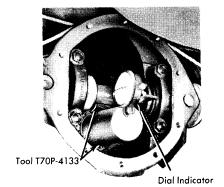 |
| FIG. 1 CHECKING DRIVE PINION DEPTH |
2) Install dummy pinion (part of special tool) into axle housing with pinion bearings but no shims. Lightly lubricate bearings and tighten tool until correct pinion bearing pre-load is obtained. Rotate dummy pinion several times to insure seating of bearings. It is essential that the torque reading be recorded and followed by further adjustment of drive pinion. This torque must also be checked after installation of drive pinion with collapsible spacer.
 |
| FIG. 2 EXPLODED VIEW OF CAPRI II DRIVE AXLE ASSEMBLY |
3) Mound dial indicator as mounting bracket and set to zero on dummy pinion. Slowly rotate dial indicator over cross bar of tool and read total deflection of pointer. This reading gives the exact thickness of the shims to be used. When pinion is marked "-1" or "-2" this amount must be added to indicator reading. When gear is marked "+1" or "+2" this amount must be subtracted from reading to obtain correct shim thickness. Using a micrometer, select a shim of the determined thickness.
 |
| FIG. 3 MEASURING SIDE GEAR CLEARANCE |
5) Position ring gear on differential case and locate with bolts. Pull ring gear evenly into position with bolts. Remove old bolts and install new bolts and tighten. To determine total play of differential case in axle housing. Press tapered roller bearing onto differential case in axle housing: Press tapered roller bearing onto differential case without shims after first inspecting bearing for damage. Install pressure blocks (part of tool T70P-4136) into axle housing on each side of differential case and install differential case and bearings in axle housing. Install bearing caps (number to number) and tighten attaching bolts. Now, loosen bolts and tighten finger tight.
6) Tighten pressure spindle (tool T70P-4136) to a torque of 43 INCH lbs. Rotate differential several times and recheck torque. Mount dial indicator on rear axle housing so that feeler contacts inner side of ring gear flange and zero indicator. Place pressure spindle into other side of housing and tighten to 43 INCH lbs. Read and note amount of indicator deflection and record as play of differential case in rear axle housing. Loosen pressure spindle, tilt dial indicator to side and remove differential, pressure spindle and pressure blocks.
 |
| FIG. 4 DIFFERENTIAL SET-UP, PRESSURE BLOCK AND SPINDLE INSTALLATION |
8) Slowly tighten nut. Keep checking pinion gear rotating torque (using INCH pound torque wrench) until rotating torque is equal to that noted during disassembly. Tighten an additional 2-4 INCH pounds torque for friction of new oil seal. Pinion nut torque should be to specification when pinion rotating torque is correct. If pinion nut torque is below specification and rotating torque is correct, install new collapsable spacer and repeat procedure.
 |
| FIG. 5 MEASURING RING GEAR BACKLASH |
10) Position dial indicator so that feeler contacts ring gear flange and zero indicator. Insert spind into other side of axle housing and torque to 43 INCH lbs. Read and record indicated deflection on indicator as ring gear back side shim thickness. Remove pressure spindle, differential case and pressure blocks from axle housing.
11) To calculate shim thickness, first take the value of differential case total play obtained in step 6) and add to this value a value for ring and pinion backlash which will give an even number. For example, if total play is .0529" (1.344 mm), add for preload the value .0021" (.056 mm) (preload value selected from specified range) to obtain .055" (1.40 mm). Next, take the value for ring gear back side shim thickness, measured in step 10), and subtract .005" (.13 mm) from this value. For example, if ring gear back side shim thickness is .0025" (.64 mm), subtract .005" (.13 mm) to obtain .020" (.51 mm). Now subtract value just obtained (.020" or .51mm) from total play value obtained above (.055" or 1.40 mm) to obtain ring gear face side shim pack, in this example .035" (.89 mm).

13) Position dial indicator feeler in a vertical position on one ring gear tooth and check that pinion to ring gear backlash is to specifications. If not, differential must be removed and shims adjusted. If backlash is to great, remove shims from ring gear back side and vise versa. Do NOT increase or decrease number of shims, but only interchange between one side and the other.
14) Finally check gear tooth contact pattern and adjust as necessary to obtain correct pattern. Position housing cover and new gasket on axle housing and install and tighten bolts. Attach parking brake operating lever to rear axle housing and connect return spring to bracket on housing. Install rear brake assemblies on axle housing and connect parking brake cable to brake assemblies
Subscribe to:
Post Comments (Atom)
No comments:
Post a Comment