Wednesday, November 30, 2011
1975 Fiat Wheel Alignment Guide
FIAT SPECIFICATIONS AND ADJUSTMENT
Before attempting to check or adjust wheel alignment, make sure tires are properly inflated. Refer to manufacturers specifications given in owner's manual.
CASTER
Model 131 and 128 (Except. Sport L) - If caster is not to specifications, raise front of vehicle. Remove stabilizer bar-to-control arm nut and disconnect control arm from body. Remove end of stabilizer bar from control arm. To adjust caster, addition of shims between end of stabilizer bar and rubber pad of control arm will decrease caster angle and removal of shims will increase caster angle. Reverse removal procedure and recheck caster.
Model 128 Sport L - If caster is not to specifications, adjust by adding or removing shims located between stabilizer bar bushing and frame.
Model 124 - If caster is not within specifications, raise front of vehicle and remove wheel and shock absorber. Using suitable tool (A.74174), compress spring to relieve lower control arm and loosen nuts holding control arm pivot bar to crossmember. To adjust caster, remove shims from front stud and move to rear stud to increase caster. To decrease caster, remove shims from rear stud and move shims to front stud. Reverse removal procedure and check caster.
Model X1/9 - If caster is not to specifications, adjust by adding or removing shims located between stabilizer bar and stabilizer bar support.
CAMBER
Model 124 - If camber is not within specifications, adjust by changing shims. Raise front of vehicle, remove wheel and shock absorber. Using suitable tool (A.74174), compress spring to relieve lower control arm and loosen nuts holding control arm pivot bar to crossmember. To increase camber, remove equal amount of shims from both studs and add equal amount of shims to decrease camber. NOTE - Adding or removing equal amounts of shims will not affect caster. Reverse removal procedure and check camber.
Model 128 and 131 Front - Camber is nonadjustable. If not within specifications, inspect suspension for damage and repair or replace parts as necessary.
Model 128 Rear - If rear camber is not within specifications raise rear of vehicle and compress one end of leaf spring, shifting it from flexible guide anchoring spring to control arm. Remove guide and slowly release spring. Remove nuts attaching pivot to body and loosen screw to free adjustment shims. To increase camber, add an equal number of shims on both screws attaching control arm to body. To decrease, remove equal number of shims from both screws. Reverse removal procedure and check camber.
Model X1/9 Front and Rear - Camber is nonadjustable. If not within specifications, inspect suspension for damage and repair or replace parts as necessary.
TOE-IN
Model 128, 131 and X1/9 Front - Place front wheels in straight-ahead position. If toe-in is not within specifications, loosen sleeve locking nut on tie rods. To adjust, rotate hexagon on ball pin to set toe-in specifications. Hold hexagon in position and lock nut against tie rod sleeve.
Model 128 Rear - If rear toe-in is not within specifications raise rear of vehicle and compress one end of leaf spring, shifting it from flexible guide anchoring spring to control arm. Remove guide and slowly release spring. Remove nuts attaching pivot to body and loosen screws to free adjustment shims. To increase to-in, add shims to rear screw or remove shims front front screw. To decrease, add shims to front screw or re3move shims from rear screw.
Model 124 Front - Place front wheels in straight-ahead position. If toe-in is not within specifications, loosen four clamps securing sleeves on tie rods. Rotate tie rods in opposite direction (by equal amounts) to set toe-in to specifications. Tighten clamp nuts. NOTE - Expansion slot in sleeve must coincide with clamp joint when clamp is fully tightened.
Model X1/9 Rear - If rear toe-in is not within specifications, loosen clamps securing sleeves to reaction rods. Adjust toe-in by lengthening or shortening reaction rods. Tighten clamps and recheck toe-in.


1963-73 Fiat Models Wheel Alignment Guide
1963-73 FIAT SPECIFICATIONS AND ADJUSTMENTS
TIRE INFLATION (COLD)
Before attempting to check or adjust wheel alignment, ensure that tires are inflated according to specifications

CASTER
Model 128 - If caster is not within specifications, raise front of vehicle. Remove anti-roll bar to control arm nut and disconnect control arm from body. Remove end of anti-roll bar from control arm. To adjust caster, addition of shims between end of anti-roll bar and rubber pad of control arm will decrease caster and removal of shims will increase caster. Reverse removal procedure and check caster.
Model 124 - If caster is not within specifications, raise front of vehicle and remove wheel and shock absorber. Using suitable tool (A.741174), compress spring to relieve lower control arm and loosen nuts holding control arm pivot bar to crossmember. To adjust caster, remove shims from front stud and move to rear stud to increase caster. To decrease caster, remove shims from rear stud and move shims to front stud. Reverse removal procedure and check caster.
Models 600D, 850 and 1100R - If caster is not within specifications, loosen two nuts on control arm pivot bar to body. To adjust, remove shims from rear stud and place shims at front stud to increase caster. To decrease caster, move shims from front stud to rear stud. Tighten nuts and check caster.
Model 1500 - No adjustment procedure available.
CAMBER
Model 124 - If camber is not within specifications, adjust by changing shims. Riase front of vehicle, remove wheel and shock absorber. Using suitable tool (A.74174), compress spring to relieve lower control arm and loosen nuts holding control arm pivot bar to crossmember. To increase camber, remove equal amount of shims from both studs and add equal amount of shims to decrease camber. NOTE - Adding or removing equal amounts of shims will not affect caster. Reverse removal procedure and check camber.
Model 1500 - No adjustment procedure available at time of this publication. See Wheel Alignment specifications.

Model 128 - Front - Camber is nonadjustable. If not within specifications, inspect suspension for damage. Repair or replace parts as necessary.
Model 128 Rear - If rear camber is not within specifications raise rear of vehicle and compress one end of leaf spring, shifting it from flexible guide anchoring spring to control arm. Remove guide and slowly release spring. Remove nuts attaching pivot to body and loosen screw to free adjustment shims. To increase camber, add an equal number of shims on both screws attaching control arm to body. To decrease, remove equal number of shims from both screws. Reverse removal procedure and check camber.
Models 600D, 850 and 1100R Front - If camber is not within specifications, adjust by changing shims. Loosen two nuts on control arm pivot bar to body. To increase camber, add equal amounts of shims to both studs and to decrease, remove equal amounts of shims. Tighten nuts and check camber.
TOE-IN
Model 128 Front - Place front wheels in straight-ahead position. If toe-in is not within specifications, loosen sleeve locking nut on tie rods. To adjust, rotate hexagon on ball pin to set toe-in specifications. Hold hexagon in position and lock nuts against tie rod sleeve.
Model 128 Rear - If rear toe-in is not within specifications raise rear of vehicle and compress one end of leaf spring, shifting it from flexible guide anchoring spring to control arm. Remove guide and slowly release spring. Remove nuts attaching pivot to body and loosen screws to free adjustment shims. To increase toe-in, add shims to rear screw or remove shims from front screw. To decrease, add shims to front screw or remove shims from rear screw.
All Other Models Front - Place front wheels in straight ahead position. If toe-in is not within specifications, loosen four clamps securing sleeves on tie rods. Rotate tie rods in opposite direction (by equal amounts) to set toe-in to specifications. Tighten clamps. NOTE - Expansion slot in sleeve must coincide with clamp joint when clamp is fully tightened.
Model 600D and 850 Rear - If rear is not within specifications, loosen screws securing lower control arm support to body. Elongated holes on support allow movement to set toe-in to specifications. Tighten screws 29-36 ft lbs. and check toe-in.
Tuesday, November 29, 2011
1974-75 Nissan Datsun Wheel Alignment Guide
DATSUN SPECIFICATIONS AND ADJUSTMENTS
TIRE INFLATION (COLD)
Before attempting to check or adjust wheel alignment, make sure that tires are properly inflated. Refer to manufacturer's specifications given in owner's manual.
RIDING HEIGHT
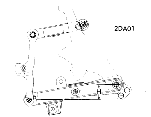
Pickup Only - Measure distance from center of lower control arm bushing (where it connects to body) and lower steering knuckle bushing (see illustration). To adjust, raise vehicle to release tension on anchor bolt adjusting nut and turn anchor bolt to adjust to specified height.
Riding Height Specifications
Application Inches (mm)
620 Pickup................................ 3.1-3.2 (72-82)
CASTER
All Models Exc. Pickup - Preset at factory and cannot be adjusted. If not to specifications, check suspension for wear or damage and repair or replace components as necessary.
Pickup - Caste is adjusted by increasing or decreasing thickness of shims inserted between upper link spindle and upper link mounting bracket. When front shim thickness increases, caster decreases. NOTE - Do not adjust caster with difference between front and rear shim thicknesses beyond .078" (2mm).
CAMBER
All Models (Exc. Pickup) - Preset at factory and cannot be adjusted. If not to specifications, check suspension for wear or damage and repair or replace components as necessary.
Pickup - Camber is adjusted bye increasing or decreasing the thickness of shims inserted between upper link spindle and upper link mounting bracket. When thickness of shims increase, camber decreases.
TOE-IN
All Models - Adjust by loosening each side steering link lock nut and adjusting steering link to change toe-in.
NOTE - Left and right side steering links should be adjusted equally. Tighten lock nuts.
1974 Datsun Models

1975 Nissan Datsun

1962-72 Nissan Datsun Wheel Alignment Guide
1962-72 DATSUN SPECIFICATIONS AND ADJUSTMENTS
TIRE INFLATION (COLD)Before attempting to check or adjust wheel alignment, ensure that tires are properly inflated.

RIDING HEIGHT
Pickups Only - Adjust to specificied distance by turning anchor bolt adjusting nut. Raise vehicle to release tension on adjusting nut.
 |
| Riding Height Measuring Point |
CASTER
All Models (Except 240Z, 510 and 1200) - Caster is adjusted by increasing or decreasing the thickness of shims inserted between upper link spindle and upper link mounting bracket. When front shim thickness increases, caster reduces. Set caster to specifications given in table. NOTE - Do not adjust caster with difference between front and rear shim thicknesses beyond .078".
240Z, 510 and 1200 - Caster is not adjustable. If alignment is not within specifications, check for damaged parts and replace as necessary
CAMBER
All Models (Except 240Z, 510 and 1200) - Camber is adjusted by increasing or decreasing the thickness of shim inserted between upper link spindle and upper link mounting bracket. When thickness of shims increases, camber reduces. Set camber to specifications given in table.
240Z, 510 and 1200 (Front) - Camber is not adjustable. If alignment is not within specifications, check for damaged parts and replace as necessary.
240Z and 510 (Rear) - Camber is not adjustable. If alignment is not within specifications, check for damaged parts and replace as necessary.
TOE-IN
All Models (Except Pickups) - Adjust by loosening side rod lock nuts and adjusting length of side rod to change toe-in to correct specifications. NOTE - Left and right side rods should be moved equally. Tighten lock nuts.
Pickups - Adjust by loosening cross rod lock nuts and turning cross rod to change its length which will increase or decrease the toe-in depending on the direction rod is turned. With toe-in to correct specifications, tighten lock nuts.

1971-72 Cricket Wheel Alignment Guide
1971-72 CRICKET SPECIFICATIONS AND ADJUSTMENTS
TIRE INFLATION
Before attempting to check or adjust front wheel alignments, ensure tires are properly inflated. Manfucturer recommended tire pressure is stenciled on inside of glove box door.
CASTER
Caster is not adjustable. If alignment is not within specification, inspect for damage parts and replace as necessary.
CAMBER
Camber is not adjustable. If alignment is not within specifications, inspect for damaged parts and replace as necessary.
TOE-IN
To adjust toe-in, loosen ball joint lock nuts on both tie rods. Loosen screws in rubber boot on inner ends of tie rod and ensure boots are free. Adjust tie rods to specifications (see chart). Tighten lock nut on tie rod end joints and center tie rods. Align boots and tighten clamps until boots are secure.

Monday, November 28, 2011
1972-76 Courier All Models Wheel Alignment Guide
1972-73 COURIER SPECIFICATIONS AND ADJUSTMENTS
TIRE INFLATION
Before attempting caster or camber adjustments, ensure tires are correctly inflated. Specifications are located on glove box door; especially consider radial tires, they require a different pressure than conventional tires.
NOTE - For reliable vehicle control, maintain specified difference between front and rear tire pressure.
NOTE - Vehicle must be unloaded, except fuel, water, and oil should be at their proper levels.
CASTER
To correct caster, adjust shims between upper control arm and frame or turn control arm shaft until correct angle is obtained (see specifications).
CAMBER
The camber is adjusted by adding or subtracting shims between the upper control arm and frame. Shims are available in the following sizes: .040", .064", .080", and .128". Set camber to specifications as shown in chart.
TOE-IN
The upward pointing of both front wheels which is necessary at offset the effects of camber. To adjust proceed as follows.
1) Raise vehicle until front wheels clear ground. Turn wheel by hand and scribe a line in cenber of each tire tred. Measure distance between marked lines. Both measurements must be taken at equal distances from ground.
2) If distance between wheels at rear is greater than that at front, but within specifications, adjustment is correct. If adjustment is wrong, loosen clamp bolts and adjust tie rod to specifications.
NOTE - Tighten clamping bolts with bolts horizontal and below steering link to prevent interference with center steering link.
FRONT WHEEL TURNING ANGLE
Front wheels should turn 37 degrees inward and 32 degrees outward. If necessary, adjust stop screws located at steering knuckle.


TIRE INFLATION
Before attempting caster or camber adjustments, ensure tires are correctly inflated. Specifications are located on glove box door; especially consider radial tires, they require a different pressure than conventional tires.
NOTE - For reliable vehicle control, maintain specified difference between front and rear tire pressure.
NOTE - Vehicle must be unloaded, except fuel, water, and oil should be at their proper levels.
CASTER
To correct caster, adjust shims between upper control arm and frame or turn control arm shaft until correct angle is obtained (see specifications).
CAMBER
The camber is adjusted by adding or subtracting shims between the upper control arm and frame. Shims are available in the following sizes: .040", .064", .080", and .128". Set camber to specifications as shown in chart.
TOE-IN
The upward pointing of both front wheels which is necessary at offset the effects of camber. To adjust proceed as follows.
1) Raise vehicle until front wheels clear ground. Turn wheel by hand and scribe a line in cenber of each tire tred. Measure distance between marked lines. Both measurements must be taken at equal distances from ground.
2) If distance between wheels at rear is greater than that at front, but within specifications, adjustment is correct. If adjustment is wrong, loosen clamp bolts and adjust tie rod to specifications.
NOTE - Tighten clamping bolts with bolts horizontal and below steering link to prevent interference with center steering link.
FRONT WHEEL TURNING ANGLE
Front wheels should turn 37 degrees inward and 32 degrees outward. If necessary, adjust stop screws located at steering knuckle.
1972-73 Courier Models

1974-75 Courier Models

1971-75 Colt All Models Wheel Alignment
COLT SPECIFICATIONS AND ADJUSTMENTS
TIRE INFLATION (COLD)
Before attempting to check or adjust wheel alignment, ensure that tires are properly inflated. Refer to specifications in owners handbook.
CASTER
Caster is nonadjustable. If not within specifications, check front suspension for damage. Repair or replace parts as necessary.
CAMBER
Camber is nonadjustable. If not within specifications, check front suspension for damage. Repair or replace parts as necessary.
TOE-IN
Position wheels in straight-ahead position. If toe-in is not within specifications, loosen locking nuts on tie rod turn buckels. To adjust, rotate turn buckels until toe-in is within specifications. Tighten lock nuts. NOTE - Adjustment must be made equally to both sides of vehicle to maintain correct wheel lock angles; difference of tie rod length when adjusted should not exceed. 20".
1971-73 Colt Models

1974 Colt Models

1975 Colt All Models

Subscribe to:
Posts (Atom)